David Herron
Tags: MODBUS »»»» Arduino »»»»
Arduino's are very popular for DIY or IoT projects involving a small computerized controller board, some GPIO pins to read inputs from the environment or to control devices, with optional communication with remote services. Theoretically an Arduino, or for that matter larger computers like the Raspberry Pi, can replace the PLC devices commonly used in industrial control applications. Why spend several hundred dollars on an expensive PLC device when the same goal can be achieved more flexibly and inexpensively with newfangled embedded computers like the Arduino? A key to this is for an Arduino (or other embedded control computer) to interface with MODBUS and other protocols used in industrial settings. In this article we'll go over using an RS-485 Shield for Arduino, using it to communicate with the simple MODBUS temperature sensor we're using. The libraries we'll discuss in this article enable using the Arduino as either MODBUS Master or Slave. The last is interesting considering the huge variety of sensors available for Arduino. Consider a simple energy monitoring project - One can interface a CT (current transformer) to measure the current in a circuit, and directly measure the voltage using an analog input, a Sketch could read that data from the sensor, and make it available via MODBUS. An Arduino could be a very simple and inexpensive device in a MODBUS network.
Elsewhere we've used this same temperature sensor
- Read a MODBUS temperature sensor through USB-RS485 adapter on Ubuntu and Raspberry Pi
- Overview of a simple MODBUS/RTU RS-485 temperature sensor
This device is cheap enough that it's a small price-of-entry to experimenting with MODBUS on the Arduino.
To get started with Arduino and see how to wire up the LCD display being used, see:
- Arduino UNO first step, connect to your laptop, run a simple application
- Displaying text on LCD screen from the Arduino UNO
Getting the RS-485 shield and other hardware
The Arduino cannot natively connect with an RS485 network, but can do so with this shield. You must already have an Arduino, if not consider Arduino Starter Kit - English Official Kit With 170 Page Book

The shield is inexpensive and slots directly onto the Arduino. Once you get the RS485 shield, go ahead and slide it on top of the Arduino.
This project also assumes you have the LCD monitor we discussed in Displaying text on LCD screen from the Arduino UNO
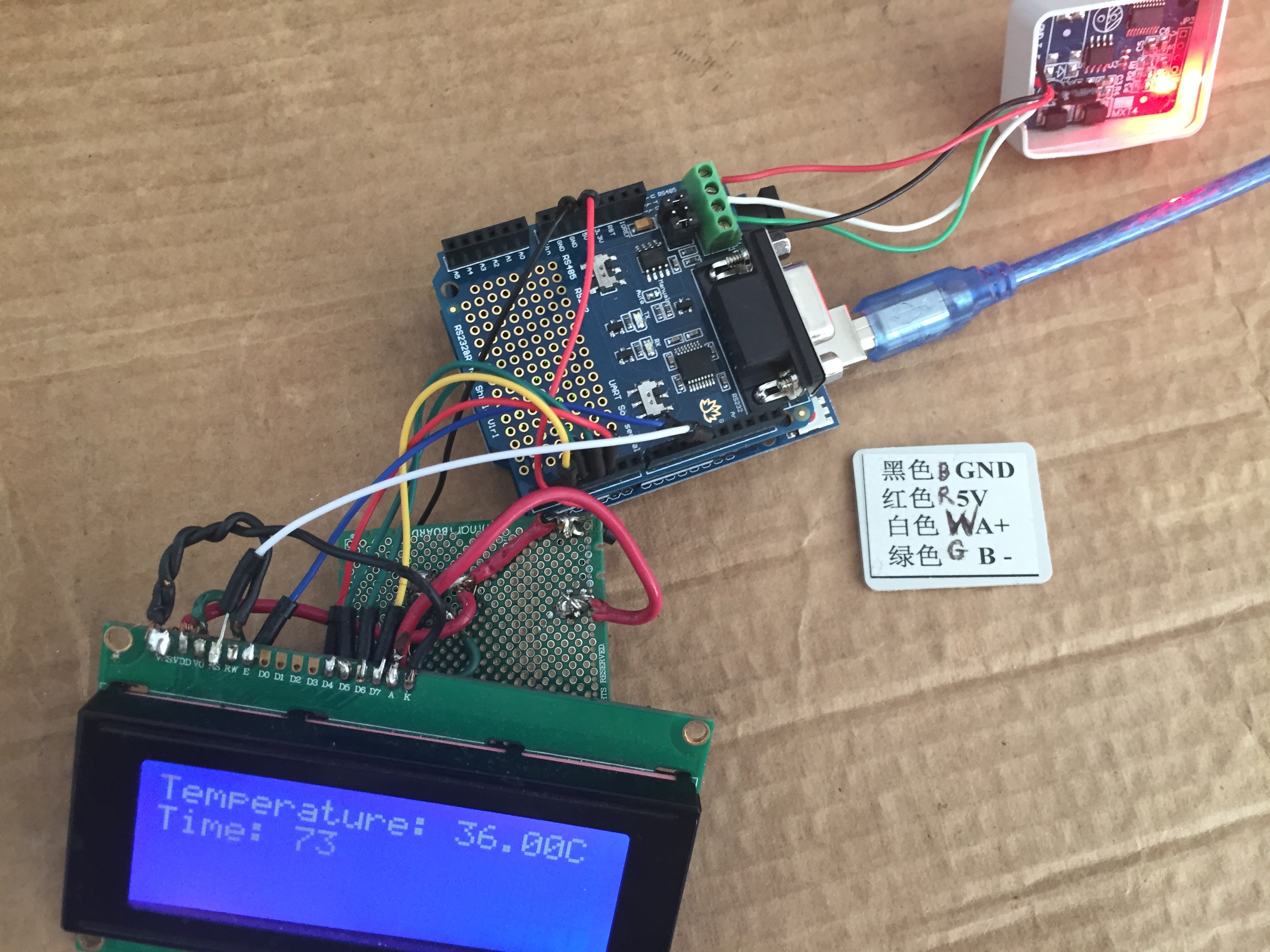
Once you have the parts assembled, it will look something like the picture at the top of the article. That picture shows the Arduino connected via USB (the blue cable) to my laptop, the temperature sensor connected to the RS485 port, and the LCD display connected to the GPIO on the RS485 shield.
Installing the ModbusMaster library for Arduino
In this project we want the Arduino to be a MODBUS Master device, and the temperature sensor will be the Slave device.
The ModbusMaster library (
https://github.com/4-20ma/ModbusMaster) does the job. With it you connect to MODBUS devices and make requests either retrieving or setting values. This library is easily installable via the Arduino IDE Library Manager, simply search for ModbusMaster. At the Github project you'll find additional examples and documentation.
Another library, Modbus Master-Slave (
https://github.com/smarmengol/Modbus-Master-Slave-for-Arduino), can make an Arduino act as a MODBUS slave device. For example you could attach a bunch of sensors, write a Sketch to read values from the sensors, making their values available over the MODBUS protocol to MODBUS master devices.
An Arduino application to read a MODBUS temperature sensor, displaying on the LCD screen
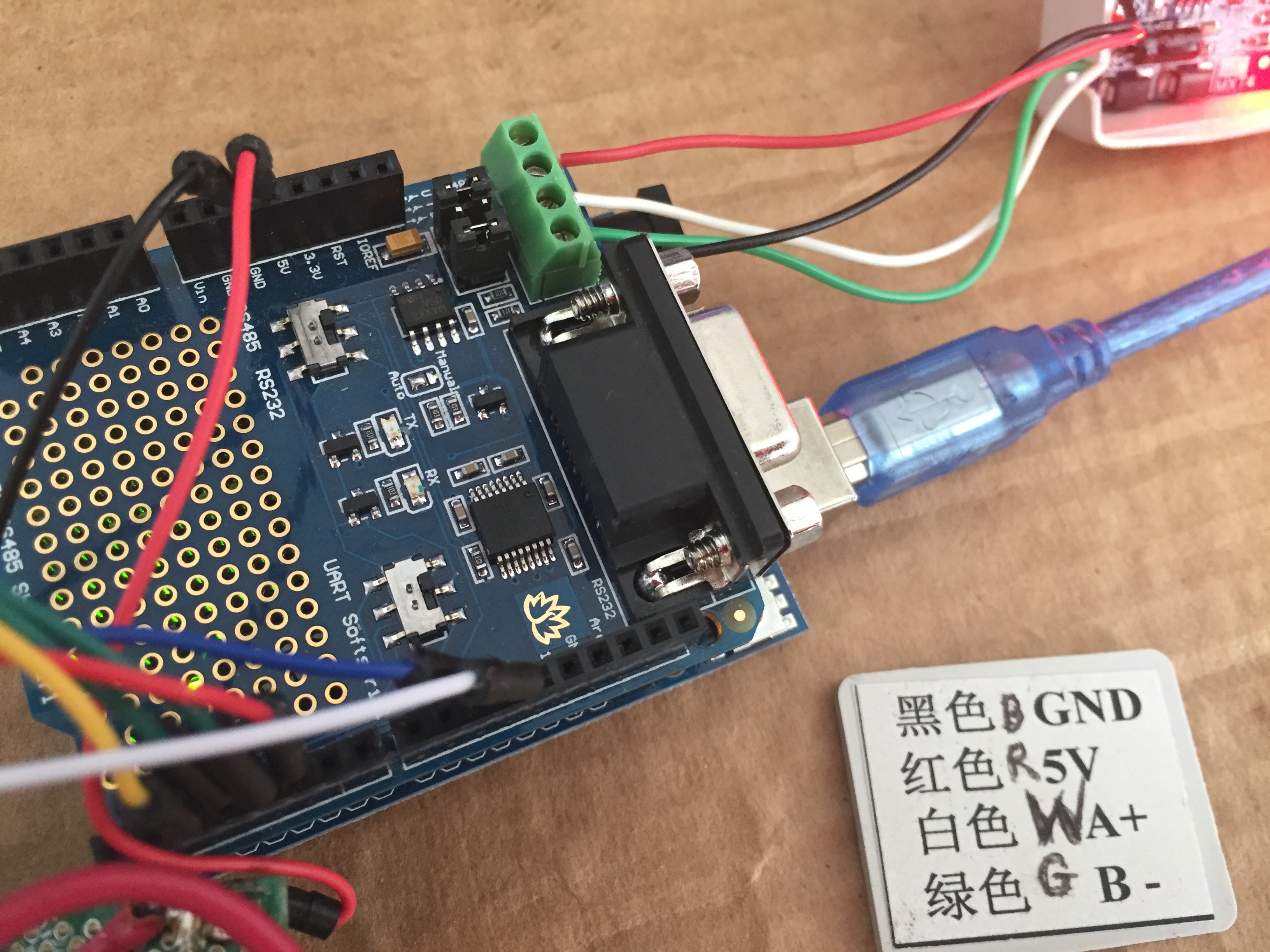
It is very simple to wire the temperature sensor to the RS485 shield. The shield conveniently provides the +5 volts and Ground required to power the sensor. Simply match the wires from the sensor to the clearly labeled connections on the shield.
In the Arduino IDE, start a new Sketch. Name it something memorable like LCD_MODBUS_Temp_Sensor_01.
// include the library code:
#include <LiquidCrystal.h>
#include <ModbusMaster.h>

// initialize the library with the numbers of the interface pins
LiquidCrystal lcd(12, 11, 5, 4, 3, 2);

// instantiate ModbusMaster object
ModbusMaster node;
We'll be taking the program section by section, so keep appending to the same Sketch. In this section we're setting up the LiquidCrystal and ModbusMaster libraries.
// variable
int tp_lcd;
int tp_modbus;
int tp_status;
uint32_t i;
These global variables will hold information we'll display on the LCD. The value in tp_lcd is what's actually to be displayed, while the value in tp_modbus is what was read from the MODBUS device, and tp_status contains the status flag from when that value was read.
void setup() {
  lcd.begin(20, 4);   // init display

  // init vars
  tp_lcd = 0;
  tp_modbus = 0;
  i = 0;

  DisplayCurrentValues();

  // use Serial (port 0); initialize Modbus communication baud rate
  Serial.begin(9600);

  // communicate with Modbus slave ID 255 over Serial (port 0)
  node.begin(1, Serial);
}
The setup function is run once, of course. We initialize the display parameters and the global variables. The DisplayCurrentValues will be shown later, and it takes care of displaying values on the screen. Then we set up the RS485 port for use with MODBUS so we can read the temperature sensor.
void loop() {
  // read modbus data
  uint8_t j, result;
  uint16_t data[6];

  i++;

  // set word 0 of TX buffer to least-significant word of counter (bits 15..0)
  node.setTransmitBuffer(0, lowWord(i));

  // set word 1 of TX buffer to most-significant word of counter (bits 31..16)
  node.setTransmitBuffer(1, highWord(i));

  // read holding register - temperature
  result = node.readInputRegisters(1, 1);
  if (result == node.ku8MBSuccess) {
      tp_modbus = node.getResponseBuffer(0);
  }
  tp_status = result;

  // display data on LCD
  CheckForDataChange();

  delay(1000);
}
Remember that loop is repeatedly executed, and the delay(1000) at the bottom means this will be executed once a second. In the middle we readInputRegisters to retrieve the temperature value from the sensor. Remember that in this sensor, the value is stored at input register 1, in centigrade, but multiplied by 100.
We check the status because I've seen flaky results with this temperature sensor. In CheckForDataChange ... well, let's just go ahead and look at that function.
void CheckForDataChange() {
  boolean data_has_changed = true;

  if (tp_lcd != tp_modbus) {
    data_has_changed = true;
    tp_lcd = tp_modbus;
  }

  if (data_has_changed == true) {
    DisplayCurrentValues();
  }
}
Remember that tp_lcd is the value to display on the LCD, and tp_modbus is what was read from the sensor. If they're not equal then the data has changed, and at the bottom of the function we call DisplayCurrentValues if it is different.
In other words, the function does what it bills itself to do -- it checks if any data has changed, and if so it calls DisplayCurrentValues.
void DisplayCurrentValues() {
  String tmpstr;
  String tmpstr2;
  double tp_dbl = tp_lcd / 100;

  lcd.clear();        // clear display

  if (tp_status == node.ku8MBIllegalFunction) {
    tmpstr2 = "IllFunc";
  } else if (tp_status == node.ku8MBIllegalDataAddress) {
    tmpstr2 = "IllAddr";
  } else if (tp_status == node.ku8MBIllegalDataValue) {
    tmpstr2 = "IllValue";
  } else if (tp_status == node.ku8MBSlaveDeviceFailure) {
    tmpstr2 = "SlaveFAIL";
  } else if (tp_status == node.ku8MBInvalidSlaveID) {
    tmpstr2 = "InvalSlave";
  } else if (tp_status == node.ku8MBInvalidFunction) {
    tmpstr2 = "InvalFunc";
  } else if (tp_status == node.ku8MBResponseTimedOut) {
    tmpstr2 = "TIME";
  } else if (tp_status == node.ku8MBInvalidCRC) {
    tmpstr2 = "CRC";
  } else {
    tmpstr2 = String(tp_dbl);
  }
  tmpstr = "Temperature: "+ tmpstr2 +"C";
  lcd.setCursor(0,0);
  lcd.print(tmpstr);

  lcd.setCursor(0,1);
  lcd.print("Time: "+ String(millis() / 1000));
}
Finally we get to see DisplayCurrentValues. In this function we display the temperature and the timestamp (seconds) since the Arduino was booted. If an error occurred, an error code is printed instead.
Loading the program into the Arduino
The RS485 shield gives us an extra step to perform whenever uploading a program. To do the upload, we must first set the UART switch on the shield to Soft Serial. With it in Soft Serial, first press the Verify button then the Upload button in the IDE. If all went well, the program will compile and then successfully upload.
As soon as it does the Arduino display will begin showing the display. Except it will say "TIME" in the Temperature field, because the switch is set to Soft Serial. It must be reset to UART in order to communicate with the temperature.
As soon as this switch is set to UART the display will begin showing the temperature.
What's next
As I said - the Arduino can act as a MODBUS device itself. There's a whole slew of sensor gadgets available for Arduino, as well as relay boards, and motor controllers, and on and on. It's possible to develop custom MODBUS devices of many kinds based on Arduino's.


 6Pcs Aluminum Chips VGA RAM Cooling Cooler Heatsink for IC MOSFET SCR,DIY for Raspberry Pi")