; Date: Wed Jun 07 2017
Tags: MODBUS »»»» Raspberry Pi »»»»
We want to experiment and learn about controlling MODBUS devices from devices like the Raspberry Pi or Arduino. In traditional process control systems, you use a PLC device costing several hundred dollars, and programmed with "ladder logic". Today single-board-computers are cheap, and are attractive for embedded control systems. Without breaking the bank, I found some ultra-cheap MODBUS temperature sensors made in China, available for about $10, and after some trial and error and more error, I have some success to report. In this post we'll simply go over the device I chose. With any MODBUS/RTU device it's important to evaluate the setup and use of the device. What serial-line parameters to use (baud rate, parity, stop bits, etc), setting the client ID, and the registers which can be used, are all basic considerations. While this post looks at a specific device, the general outline of the evaluation is what is done for every MODBUS device.
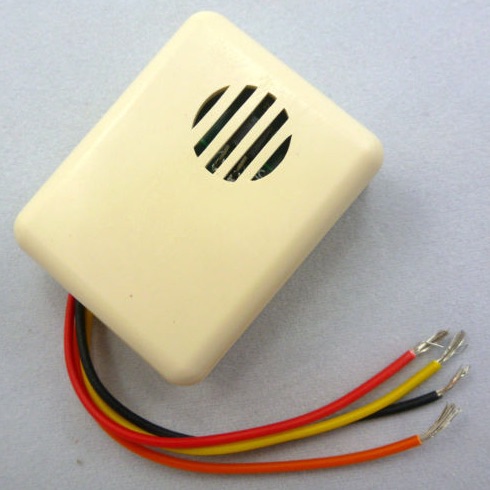
The price (about $10) was attractive in that "that's so cheap, what do I have to lose" way. Unfortunately the device wasn't documented. Fortunately, contacting the seller gave me some documentation, which we'll go over here.
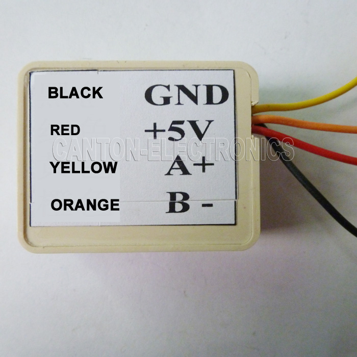
That's the extent of the documentation in the online store (eBay) where I bought this device. This much does tell us one thing:
- Power: 5 volts
And we know the color code for the wires.
A query to the seller gave me a
link to the product page on their website, and the model number: TB111. And, he gave a URL to download a product manual: http://www.canton-electronics.com/pdf/TB111 modbus.zip

Now we can start reading the manual to determine settings and other information:
- Power: 5 volts
- 9600 baud,No parity,8 bits,1 stop bit
That gives us enough to configure software to communicate with the device. But it doesn't tell us the all-important device ID.
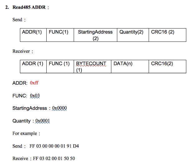
What device ID to use? The manual isn't entirely clear on that, but it does offer this register.
The documentation says to send to device ID 0xFF (255) at address 0x0000 the value you want to set as the device ID. There are two problems with this:
- Device ID 255 is beyond the upper bound for allowable device ID's (247 is the maximum value). Libmodbus refuses to allow software to read from that device ID
- Similarly reading from register
0x00is not supported by libmodbus.
It seems impossible to set this value, and that leaves us wondering if there's a default device ID, and what would it be.
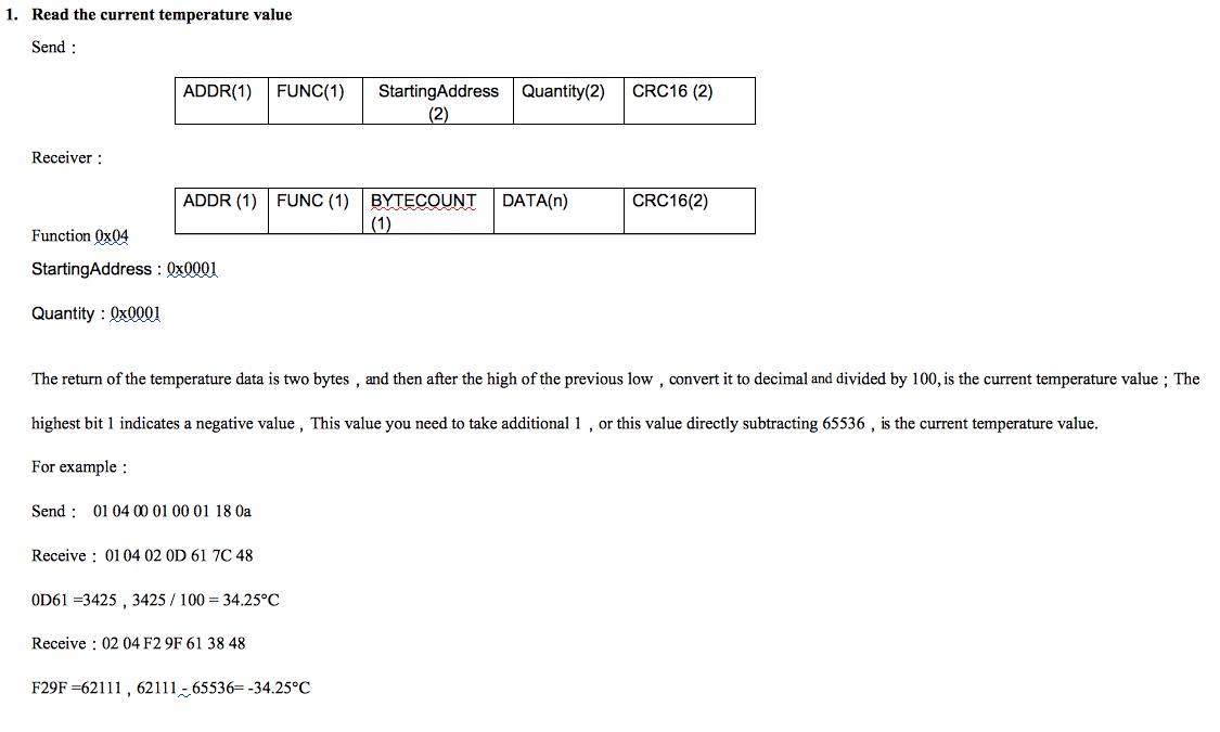
Before we discuss reading the temperature value, this section gives us a clue about the default device ID.
You'll notice in the hex dump of the protocol exchange, that device ID 01 is used. Nothing in the manual is said about this value, however every example uses device ID 01. I've confirmed, by experimenting with software, that 01 is the correct device ID.
Reading the temperature is fairly simple. You use function code 0x04 (read holding register), at address 0x01 with a length of 0x01. The reply is two bytes, and you're supposed to divide by 100. For example it might reply with 3137, and after dividing by 100 you get 31.37 which is the temperature in Centigrade.
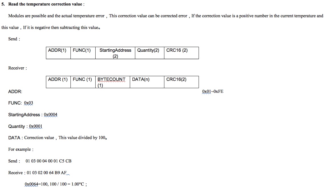
You might try to verify that this unit gives an accurate temperature reading. It's a cheap Chinese product that looks completely unreliable, so clearly the temperature is likely to be wrong. This register (function code 0x03, read input registers) gives a correction factor which is either positive or negative and appears to be a number to be added/subtracted to/from the reported value.
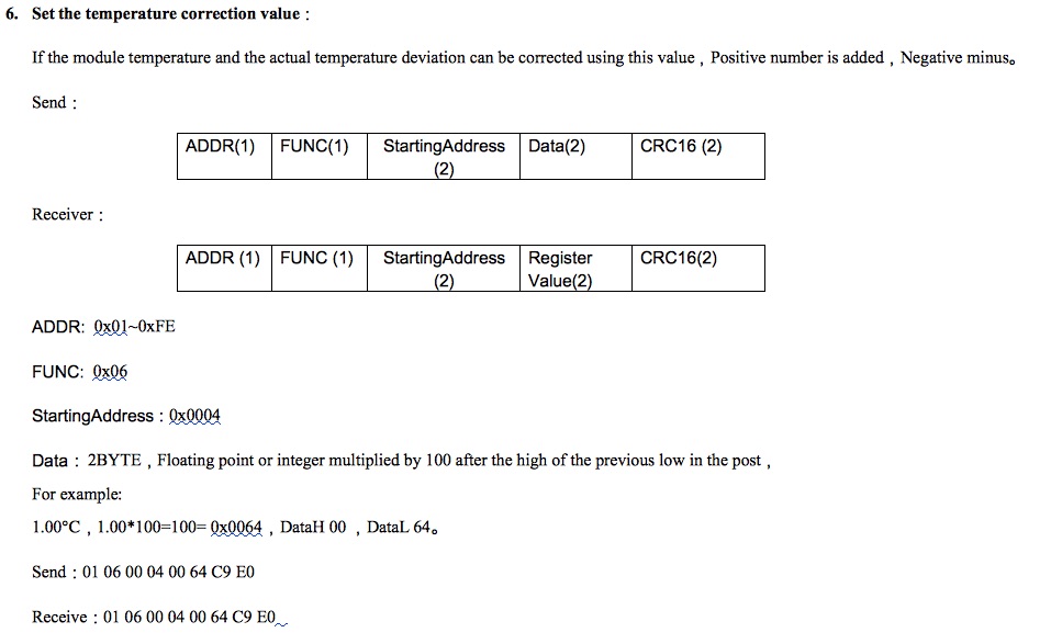
This is how you set the temperature correction factor, by using function code 0x06 to send a value to address 0x04.
Summary
There are two more commands to set the device ID and to set the baud rate. That's not terribly important since you're almost certainly not going to use this device in a production setting. To be honest it's not a high quality MODBUS device, and it's best use is for experimenting and learning.


