David Herron
Tags: MODBUS »»»» Raspberry Pi »»»»
Running MODBUS/RTU over an RS485 network is pretty cool, in an old-school way. The technique was invented decades ago, and allowed you to connect to a few dozen MODBUS devices over simple twisted pair copper wire, over a thousand feet distance or more. It's such a successful technique that it has not been supplanted by new modern communication technologies like TCP/IP. Unfortunately most modern computers do not have RS-485 interfaces. Fortunately there are many USB-RS485 adapters available. In this article we'll use a cheap USB-RS485 adapter on both a Raspberry Pi and a regular x86 Linux box to communicate with a simple MODBUS temperature sensor. What we'll do is create simple MODBUS client programs, in C and Python, to communicate with the chosen temperature sensor device.
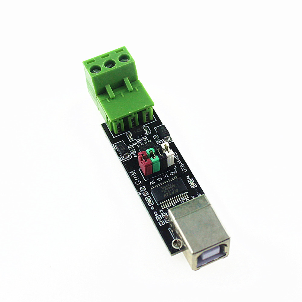
For this project, we're using a cheap MODBUS temperature sensor that's probably not suitable for production use, but is good enough for small scale experimentation and learning. (See Overview of a simple MODBUS/RTU RS-485 temperature sensor) Additionally we're using this USB-to-RS485 adapter card:

I've only used this device on Ubuntu, Raspbian (Raspberry Pi), and Mac OS X. Essentially you plug it into a USB port on your computer, and attach a MODBUS device to the jumper block, then run MODBUS software. On those operating systems a /dev/ttySOMETHING device is automatically set up, which you'll have to determine from the system log. The software has to connect through that device, and most of the details are automatically taken care of for you.
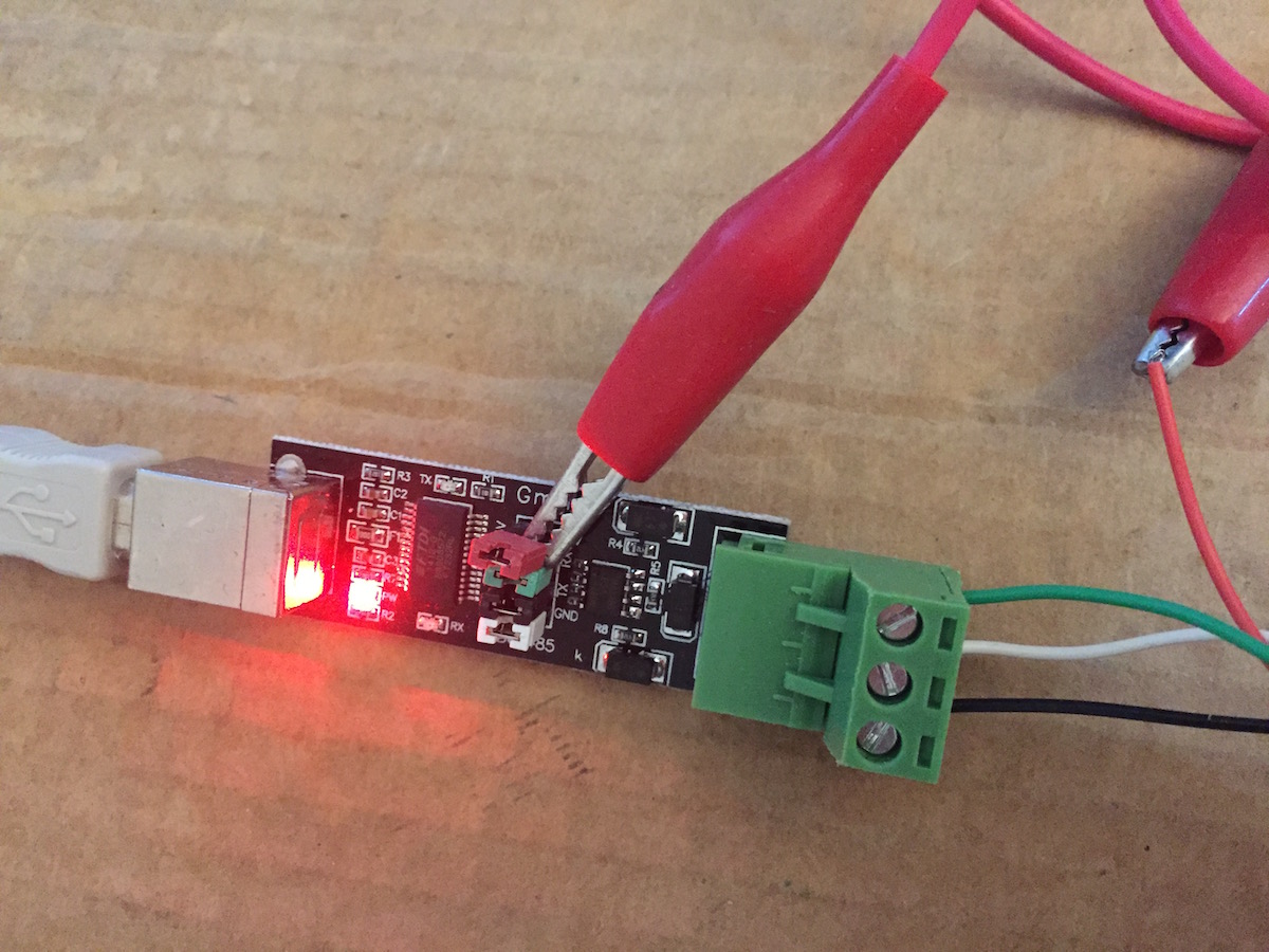
Close-up pictures:
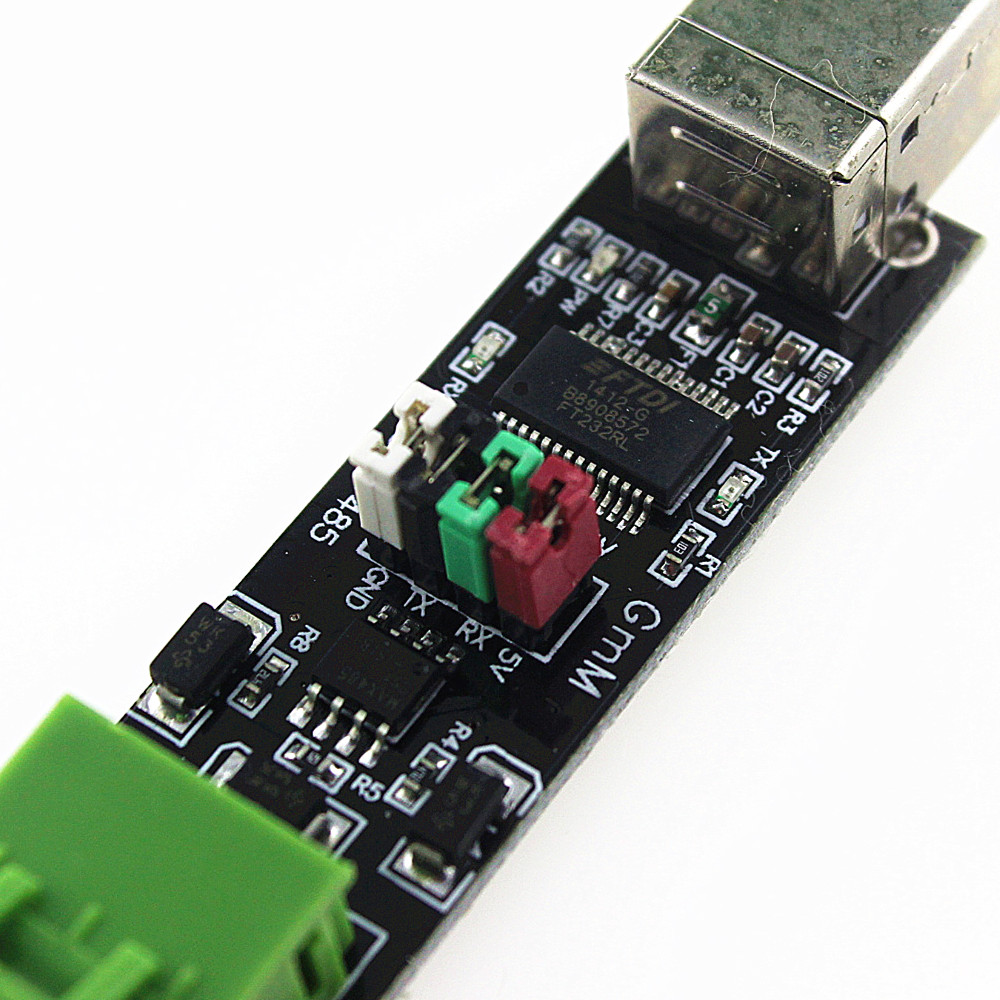
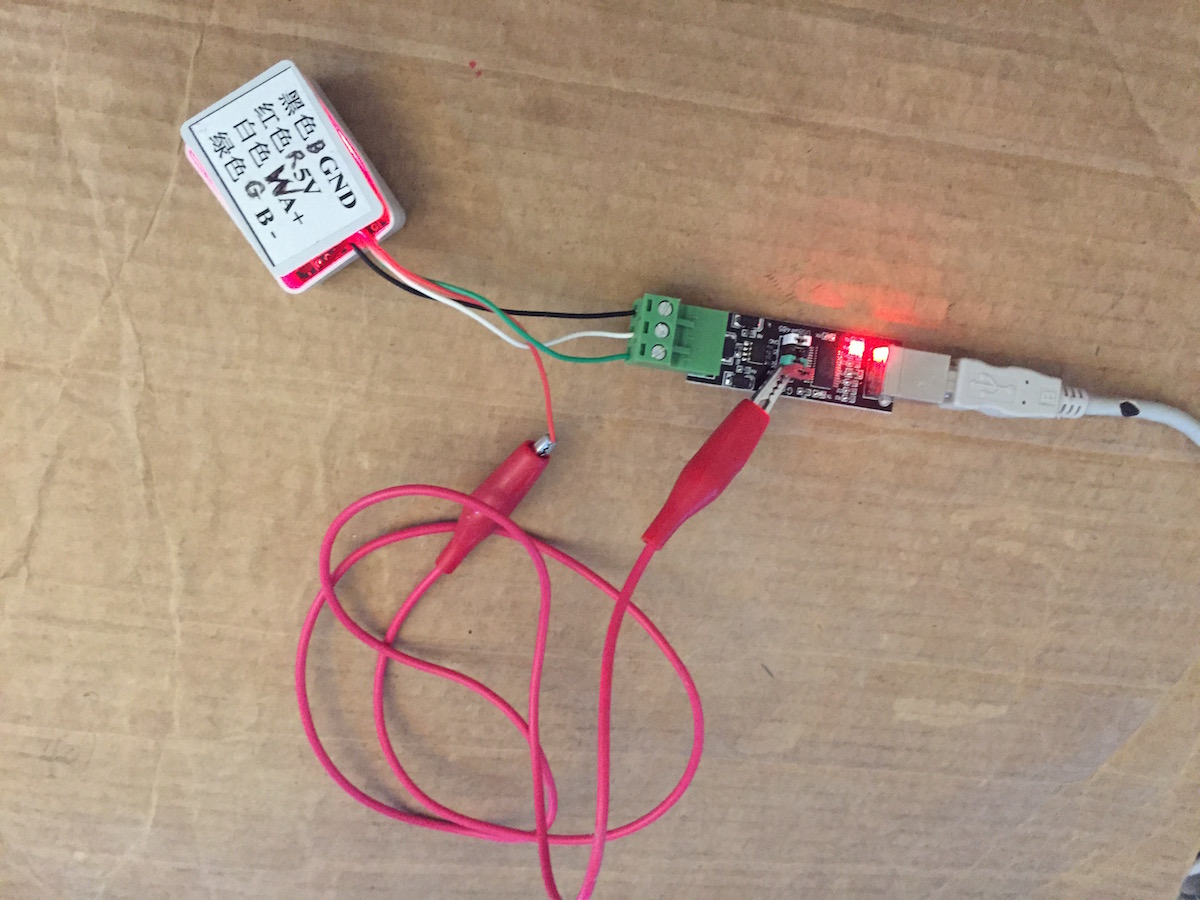
These pictures show details of wiring the USB-to-RS485 adapter with this particular MODBUS device.
The device requires a 5 volt power supply, and the simplest way to get that power is via the jumper on the adapter board. The manufacturer did not bring the 5 volt connector out to the jumper block, but it is available there on the jumper pin. It's just a matter of connecting to that jumper pin using an extension cord. Otherwise "A" on the device is connected to "A" on the adapter, "B" on the device is connected to "B" on the adapter, as is "GND".
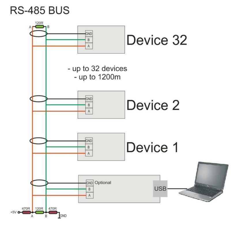
In theory this is how you connect multiple devices to this adapter. I have not tried this, however. It appears from the diagram that in this case, you're to use shielded cable, and the GND connection on each adapter board is to be connected to shield, which would then be connected to ground somewhere.
Connecting the USB-RS485 adapter, learning the device name
On connecting the device to a USB port, the Linux/Unix kernel will scan the device and figure out what it is. For Linux, the device is automatically recognized (usually) and a series of messages like this might be printed:
May 31 13:49:02 nuc1 kernel: [ 2964.249228] usb 1-2: new full-speed USB device number 12 using xhci_hcd
May 31 13:49:02 nuc1 kernel: [ 2964.383074] usb 1-2: New USB device found, idVendor=0403, idProduct=6001
May 31 13:49:02 nuc1 kernel: [ 2964.383086] usb 1-2: New USB device strings: Mfr=1, Product=2, SerialNumber=3
May 31 13:49:02 nuc1 kernel: [ 2964.383093] usb 1-2: Product: FT232R USB UART
May 31 13:49:02 nuc1 kernel: [ 2964.383100] usb 1-2: Manufacturer: FTDI
May 31 13:49:02 nuc1 kernel: [ 2964.383107] usb 1-2: SerialNumber: A91P30SH
May 31 13:49:02 nuc1 kernel: [ 2964.387488] ftdi_sio 1-2:1.0: FTDI USB Serial Device converter detected
May 31 13:49:02 nuc1 kernel: [ 2964.387641] usb 1-2: Detected FT232RL
May 31 13:49:02 nuc1 kernel: [ 2964.389048] usb 1-2: FTDI USB Serial Device converter now attached to ttyUSB1
The last line says the device name, in this case /dev/ttyUSB1.
If you should need to know, the manufacturer is at:
http://www.ftdichip.com/ Their chips are in a wide variety of products, and there is driver software on their site if you need it.
Programming a MODBUS device in C with libmodbus
Okay, enough with setup let's get on with some code. We'll start with libmodbus because it's universally available, see
http://libmodbus.org/
For Ubuntu, and on Raspbian, you install the libmodbus-dev and libmodbus5 packages:
$ sudo apt-get install libmodbus5 libmodbus-dev
Once installed, we have this code for your perusal:
#include <stdio.h>
#include <unistd.h>
#include <string.h>
#include <stdlib.h>
#include <errno.h>
#include <modbus-rtu.h>

const int EXCEPTION_RC = 2;

enum { TCP, TCP_PI, RTU };

#define SERVER_ID 1

int main(int argc, char *argv[]) {
    modbus_t *ctx = NULL;
    uint16_t *tab_rp_bits = NULL;
    struct timeval old_response;
    struct timeval new_response;
    uint32_t old_response_to_sec;
    uint32_t old_response_to_usec;
    uint32_t new_response_to_sec;
    uint32_t new_response_to_usec;
    uint32_t old_byte_to_sec;
    uint32_t old_byte_to_usec;
    int rc;
    int server_id = SERVER_ID;

    // UPDATE THE DEVICE NAME AS NECESSARY
    ctx = modbus_new_rtu("/dev/ttyUSB0", 9600, 'N', 8, 1);
    if (ctx == NULL) {
        fprintf(stderr, "Could not connect to MODBUS: %s\n", modbus_strerror(errno));
        return -1;
    }

    printf("Setting slave_id %d\n", server_id);
    fflush(stdout);
    rc = modbus_set_slave(ctx, server_id);
    if (rc == -1) {
        fprintf(stderr, "server_id=%d Invalid slave ID: %s\n", server_id, modbus_strerror(errno));
        modbus_free(ctx);
        return -1;
    }
    modbus_set_debug(ctx, TRUE);
    // Not needed for USB-RS485 adapters
    // See: https://github.com/stephane/libmodbus/issues/316
    /* rc = modbus_rtu_set_serial_mode(ctx, MODBUS_RTU_RS485);
    if (rc == -1) {
        fprintf(stderr, "server_id=%d Failed to set serial mode: %s\n", server_id, modbus_strerror(errno));
        // modbus_free(ctx);
        // return -1;
        server_id++;
        goto retry_slave;
    } */
    modbus_set_error_recovery(ctx,
                              MODBUS_ERROR_RECOVERY_LINK |
                              MODBUS_ERROR_RECOVERY_PROTOCOL);

    modbus_get_response_timeout(ctx, &old_response /* &old_response_to_sec, &old_response_to_usec /* */);
    if (modbus_connect(ctx) == -1) {
        fprintf(stderr, "Connection failed: %s\n", modbus_strerror(errno));
        modbus_free(ctx);
        return -1;
    }
    modbus_get_response_timeout(ctx, &new_response /* &new_response_to_sec, &new_response_to_usec /* */);

    tab_rp_bits = (uint16_t *) malloc(2 * sizeof(uint16_t));
    memset(tab_rp_bits, 0, 2 * sizeof(uint16_t));

    while (TRUE) {
        rc = modbus_read_input_registers(ctx, 0x1, 0x1, tab_rp_bits);
        if (rc == -1) {
            fprintf(stderr, "Failed to modbus_read_input_registers: %s\n", modbus_strerror(errno));
            /* modbus_free(ctx);
            return -1; */
        }

        printf("server_id=%d rc=%d temp=%f \n", rc, server_id, (double)(tab_rp_bits[0] / 100.0));
        sleep(1);
    }

close:
    /* Free the memory */
    free(tab_rp_bits);
    // free(tab_rp_registers);

    /* Close the connection */
    modbus_close(ctx);
    modbus_free(ctx);

    return 0;
}
Remember the device we're using is addressed as device ID 1, and we are to read register 1 for the temperature value.
The modbus_new_rtu function creates a MODBUS/RTU object. With modbus_set_slave we set the device ID to work with, and with modbus_connect we connect to the device.
There is a commented-out section where we would call modbus_rtu_set_serial_mode. With the USB adapter we have, the settings controlled by that function are handled for us automatically, and if we call that function errors will be generated.
With this:
tab_rp_bits = (uint16_t *) malloc(2 * sizeof(uint16_t));
memset(tab_rp_bits, 0, 2 * sizeof(uint16_t));
We set up a buffer to receive data from the MODBUS device. Each MODBUS register is 16 bits (a.k.a. "1 word") and we've allocated space for two registers. You should of course allocate space depending on the number of registers you'll be reading.
Then, in a loop, with a 1-second delay per iteration, we call modbus_read_input_registers to read from the device. Output is shown below.
The modbus_get_response_timeout and modbus_get_response_timeout functions have different signatures depending on the libmodbus version. To accommodate that difference we've got code you can comment/uncomment to match the library version.
To compile the program, type this:
$ gcc -o temp temp.c `pkg-config --cflags --libs libmodbus`
Then run it as so:
$ sudo ./temp
[sudo] password for david:
server_id=1 rc=1 temp=30.750000
server_id=1 rc=1 temp=30.750000
server_id=1 rc=1 temp=30.750000
server_id=1 rc=1 temp=30.750000
Reading the temperature in MODBUS device using minimalmodbus in Python
Compared to the libmodbus example using minimalmodbus in Python will feel like a nice cool breeze. This library makes MODBUS programming very simple, though it is on the limited side.
Library documentation is at:
minimalmodbus readthedocs io
Installation:
$ pip install minimalmodbus
Then type this in as temp.py
#!/usr/bin/env python
import minimalmodbus
import time

minimalmodbus.BAUDRATE = 9600

# port name, slave address (in decimal)
instrument = minimalmodbus.Instrument('/dev/ttyUSB0', 1)

while True:
    # Register number, number of decimals, function code
    temperature = instrument.read_register(1, 2, 4)
    print temperature
    time.sleep(1)
Before setting up the MODBUS connection, it's possible to set connection parameters (baud rate, etc) by assigning values to the minimalmodbus object. Then you connect to the device, minimalmodbus.Instrument, and interact with it using the API.
The instrument.read_register command reads a single register, to read multiple registers use instrument.read_registers. It takes the register number, and an indicator of the number of decimal points, and finally the function code. Function code 4 reads from the Holding Registers, of course.
The number of decimal points is the same issue where we divided by 100.0 in the C code. This device stores the temperature in Centigrade, but as an integer 100x than the actual value. For display you divide by 100, and automatically get two digits of precision.
Output will look like this:
$ sudo python temp.py
25.37
25.37
25.43
25.43
25.5
25.56
25.56
25.62
Reading the temperature in MODBUS device using pymodbus in Python
The pymodbus library is far more comprehensive than minimalmodbus in that you can do a lot more with it. It does mean the library is harder to use.
Documentation:
pymodbus readthedocs io
Home page:
riptideio github io
Installation
$ pip install -U pymodbus
Type this code in as temp.py
#!/usr/bin/env python
from pymodbus.client.sync import ModbusSerialClient as ModbusClient

client = ModbusClient(method='rtu', port='/dev/ttyUSB0', timeout=1, stopbits = 1, bytesize = 8,  parity='N', baudrate= 9600)
client.connect()

while True:
    rr = client.read_input_registers(address=1, count=1, unit=1);
    print rr.registers[0] / 100.0;
In this case you pass connection parameters to the object constructor as shown here. And then you simply call client.read_input_registers. If an error occurs, rr will be a None so be careful.
Output will look like this:
$ sudo python temp.py
26.37
26.43
26.43
26.5
26.56
26.56
26.56
26.62
26.62
26.62