David Herron
Tags: Node.JS »»»» Docker »»»» Terraform »»»»
Amazon's AWS Elastic Container Service (ECS) lets us deploy Docker containers to the AWS cloud. ECS is a very complex beast to tame, but Terraform offers a way to easily describe infrastructure builds not only AWS but on many other cloud services. Using Terraform is hugely simpler than any tool offered by AWS ECS.
Terraform is a powerful tool for describing cloud application infrastructure. It supports many cloud services including AWS. The advantage of Terraform is it is fairly easily learned, and it lets us describe the AWS infrastructure configuration far more simply than we can with any tool provided by AWS. We still need to learn all the bits and bobs involved in setting up AWS infrastructure, but as we'll see the declarations are straight-forward and easy to use.
This example builds off two previous tutorials:
- A simple multi-tier Node.js and Nginx deployment using Docker
- Deploying a simple multi-tier Node.js and Nginx deployment to AWS ECS
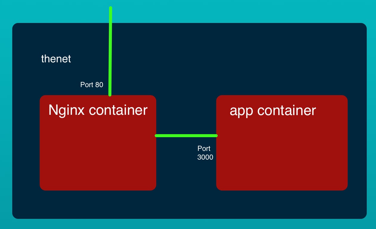
The example code is a two-container system that roughly mimics a multi-tier application. The front tier is an NGINX server that has its HTTP port published to the world. The back tier is an extremely simple Node.js service. While it is a trivial example, either of these containers could be far more complex and there could easily be multiple back-end micro-service containers. But to get to that we must start with baby steps.
In this example we will use Terraform to deploy that stack to AWS ECS. The AWS Elastic Container Service is the AWS answer for deploying Docker containers at scale on the AWS infrastructure. While it is a powerful system, it is also extremely complex, and extremely difficult to get a working system running.
To familiarize yourself with the application stack visit the earlier tutorials.
The source code is on Github at
robogeek / aws-ecs-nodejs-sample
Setting up AWS CLI tools
For this application we will be using the CLI tool for AWS very little. At the minimum we need to install and configure the AWS CLI tool so that we have AWS authentication credentials in our home directory. The AWS CLI tool is very powerful and can be used to inspect and manage AWS infrastructure.
We start by installing and configuring the AWS CLI. To install the CLI tool, see the instructions at:

The next step is to set up sign-in credentials. A pre-requisite is to set up:
- An AWS Root Account, which is the main AWS account when you sign up with the service
- Then create an IAM User Account with which we will be doing everything in the tutorial
In the IAM area you'll be able to download access key CSV files for each of these.
In the AWS CLI tool we'll create an AWS Profile for each. The AWS documentation has some discussion about this at
$ aws configure --profile PROFILE-NAME-FOR-ROOT-ACCOUNT
AWS Access Key ID [None]: AKIAIOSFODNN7EXAMPLE
AWS Secret Access Key [None]: wJalrXUtnFEMI/K7MDENG/bPxRfiCYEXAMPLEKEY
Default region name [None]: us-west-2
Default output format [None]: json
$ aws configure --profile PROFILE-NAME-FOR-IAM-USER-ACCOUNT
AWS Access Key ID [None]: AKIAIOSFODNN7EXAMPLE
AWS Secret Access Key [None]: wJalrXUtnFEMI/K7MDENG/bPxRfiCYEXAMPLEKEY
Default region name [None]: us-west-2
Default output format [None]: json
That is, the aws configure command interrogates you about the access keys, plus your desired region code and output format. The access keys were downloaded when you created the accounts. Choose a profile name to go with each account.
This creates two files ~/.aws/credentials and ~/.aws/config which are simple INI-style files containing the data you entered. In fact it's possible to create a profile just by editing these files.
For the needs of this tutorial, this is the entirety of our need for the AWS CLI tool.
Setting up Terraform
The simplest setup method is
to download Terraform from their website.
Since the base Terraform CLI is an open source tool you may find it in the various package managers. For example I found it in MacPorts. Therefore installation was as simple as:
$ sudo port install terraform
...
$ sudo port select --set terraform terraform0.12
Selecting 'terraform0.12' for 'terraform' succeeded. 'terraform0.12' is now active.
$ terraform
Usage: terraform [-version] [-help] <command> [args]

The available commands for execution are listed below.
The most common, useful commands are shown first, followed by
less common or more advanced commands. If you're just getting
started with Terraform, stick with the common commands. For the
other commands, please read the help and docs before usage.

...
Before getting to the Terraform declarations for our infrastructure, we have a task related to storing the Docker images in a useful location.

Uploading Docker containers to AWS ECR Repositories
Before we can deploy Docker containers to ECS they must be in a public Docker repository. AWS offers the Elastic Container Registry to supply you with a Docker suitable repository.
The example repository (
robogeek / aws-ecs-nodejs-sample) contains these directories:
app, containing the Node.js source of the server,nginx, containing an NGINX container for use on your laptop,ecs-terraform, containing scripts to aid deployment to ECS using Terraform, and,ecs-terraform/nginx, containing an NGINX container for deployment to ECS using Terraform.
The difference between the contents of nginx and ecs-terraform/nginx is that it is configured to connect with the Node.js back-end this way.
server { # simple reverse-proxy
    listen       80;
    location / {
        proxy_pass      http://127.0.0.1:3000/;
    }
}
For use on our laptop, the proxy_pass declaration points to http://app:3000 but here it points to 127.0.0.1. That's because of the difference between Docker bridge networking, and AWS awsvpc networking.
On a Docker bridge network the containers each have a DNS name related to the container name. For the example we're about to show, the containers are all attached to the same virtual network interface and are therefore able to reach each other via the 127.0.0.1 IP address.
In the ecs-terraform directory we have various Terraform scripts, plus a package.json required to drive the process. We'll be building the Terraform scripts over the rest of this post. Let's first focus on the build scripts.
{
    "scripts": {
        "docker-login": "aws ecr get-login-password --profile ${AWS_PROFILE} --region ${AWS_REGION} | docker login --username AWS --password-stdin ${AWS_USER}.dkr.ecr.${AWS_REGION}.amazonaws.com",
        "ecr-repositories": "aws ecr describe-repositories --profile ${AWS_PROFILE} --repository-names app nginx-ecs-terraform",
        "build": "npm run build-app && npm run build-nginx",
        "build-app": "cd ../app && npm run build",
        "build-nginx": "cd nginx && npm run build",
        "ecr-create-repos": "npm run ecr-create-app && npm run ecr-create-nginx",
        "ecr-create-app": "cd ../app && npm run create-repo",
        "ecr-create-nginx": "cd nginx && npm run create-repo",
        "ecr-tag-repos": "npm run ecr-tag-app && npm run ecr-tag-nginx",
        "ecr-tag-app": "cd ../app && npm run tag",
        "ecr-tag-nginx": "cd nginx && npm run tag",
        "ecr-push-repos": "npm run ecr-push-app && npm run ecr-push-nginx",
        "ecr-push-app": "cd ../app && npm run push",
        "ecr-push-nginx": "cd nginx && npm run push"
    }
}
Note that we're relying on the environment variables mentioned earlier. AWS_PROFILE is the AWS Profile being used, and AWS_REGION is the AWS Region to be used. The value for AWS_USER must be the IAM user ID number. This is not the IAM user name, but the numerical ID number that you'll see in the IAM dashboard.
When we create a container repository in the Elastic Container Registry, it generates for us a container repository name in the format ${AWS_USER}.dkr.ecr.${AWS_REGION}.amazonaws.com/CONTAINER-NAME. Hence the script uses that format.
Before we can run these commands a little setup is required. First, we log-in to the ECR Registry:
$ npm run docker-login

> @ docker-login /Volumes/Extra/nodejs/aws-ecs-nodejs-sample/ecs-terraform
> aws ecr get-login-password --profile ${AWS_PROFILE} --region ${AWS_REGION} | docker login --username AWS --password-stdin ${AWS_USER}.dkr.ecr.${AWS_REGION}.amazonaws.com

Login Succeeded
With that out of the way, let's talk about building the container images and uploading them to the Elastic Container Registry.
These scripts let us build the container images on our laptop:
$ npm run build
... much output
This builds the images on our laptop.
The next step is creating Docker image repositories on ECR that will store the two images.
$ npm run ecr-create-repos
... much output
This creates the repositories, which you can verify by looking at the ECR dashboard. Or, you can run this command:
$ aws ecr describe-repositories --profile ${AWS_PROFILE} --repository-names app nginx-ecs-simple
{
    "repositories": [
        {
            "repositoryArn": "arn:aws:ecr:AWS_REGION:AWS_USER:repository/app",
            "registryId": "AWS_USER",
            "repositoryName": "app",
            "repositoryUri": "AWS_USER.dkr.ecr.AWS_REGION.amazonaws.com/app",
            "createdAt": "2020-03-21T16:48:07-07:00",
            "imageTagMutability": "MUTABLE",
            "imageScanningConfiguration": {
                "scanOnPush": true
            }
        },
        {
            "repositoryArn": "arn:aws:ecr:AWS_REGION:AWS_USER:repository/nginx-ecs-simple",
            "registryId": "AWS_USER",
            "repositoryName": "nginx-ecs-simple",
            "repositoryUri": "AWS_USER.dkr.ecr.AWS_REGION.amazonaws.com/nginx-ecs-terraform",
            "createdAt": "2020-03-24T16:53:24-07:00",
            "imageTagMutability": "MUTABLE",
            "imageScanningConfiguration": {
                "scanOnPush": true
            }
        }
    ]
}
The important piece of data is the repositoryUri value. Record this for later use.
The next step is to tag the repositories, like so:
$ npm run ecr-tag-repos

> @ ecr-tag-repos /Volumes/Extra/nodejs/aws-ecs-nodejs-sample/ecs-simple
> npm run ecr-tag-app && npm run ecr-tag-nginx


> @ ecr-tag-app /Volumes/Extra/nodejs/aws-ecs-nodejs-sample/ecs-simple
> cd ../app && docker tag app:latest ${AWS_USER}.dkr.ecr.${AWS_REGION}.amazonaws.com/app:latest


> @ ecr-tag-nginx /Volumes/Extra/nodejs/aws-ecs-nodejs-sample/ecs-simple
> cd nginx && docker tag nginx:latest ${AWS_USER}.dkr.ecr.${AWS_REGION}.amazonaws.com/nginx-ecs-terraform:latest
This prepares the images for being pushed to the ECR repositories.
And finally we push the images to the repositories:
$ npm run ecr-push-repos

> @ ecr-push-repos /Volumes/Extra/nodejs/aws-ecs-nodejs-sample/ecs-simple
> npm run ecr-push-app && npm run ecr-push-nginx


> @ ecr-push-app /Volumes/Extra/nodejs/aws-ecs-nodejs-sample/ecs-simple
> cd ../app && docker push ${AWS_USER}.dkr.ecr.${AWS_REGION}.amazonaws.com/app:latest

The push refers to repository [AWS_USER.dkr.ecr.AWS_REGION.amazonaws.com/app]
4428b5a79a9b: Layer already exists
b5a31e7fd043: Layer already exists
18db616a7fac: Layer already exists
7fac39be7c83: Layer already exists
236d3097407d: Layer already exists
91daf9fc6311: Layer already exists
162804eaaa1e: Layer already exists
d040e6423b7a: Layer already exists
00adafc8e77b: Layer already exists
2c995a2087c1: Layer already exists
latest: digest: sha256:6747b12eca9485c8aceadce063c38564fe8fb45058db1455221794528c89aa42 size: 2422

> @ ecr-push-nginx /Volumes/Extra/nodejs/aws-ecs-nodejs-sample/ecs-terraform
> cd nginx && npm run push


> @ push /Volumes/Extra/nodejs/aws-ecs-nodejs-sample/ecs-terraform/nginx
> docker push ${AWS_USER}.dkr.ecr.${AWS_REGION}.amazonaws.com/nginx-ecs-terraform:latest

The push refers to repository [098106984154.dkr.ecr.us-west-2.amazonaws.com/nginx-ecs-terraform]
62a89b0c27c8: Pushed
bc21985928b6: Pushed
e370c53ec242: Pushed
f2cb0ecef392: Pushed
latest: digest: sha256:43c7a9f24236575c6bb465d04254ed53640a8ed587817776e84e7bd419792a8b size: 1155
One way to verify this worked is with docker pull:
$ docker pull AWS_USER.dkr.ecr.AWS_REGION.amazonaws.com/nginx-ecs-terraform
Using default tag: latest
latest: Pulling from nginx-ecs-terraform
Digest: sha256:43c7a9f24236575c6bb465d04254ed53640a8ed587817776e84e7bd419792a8b
Status: Image is up to date for AWS_USER.dkr.ecr.AWS_REGION.amazonaws.com/nginx-ecs-terraform:latest
AWS_USER.dkr.ecr.AWS_REGION.amazonaws.com/nginx-ecs-terraform:latest
With that taken care of we're ready to move on to the next step, which is the Terraform configured required for deploying the service on AWS ECS.
Getting started with Terraform
The syntax for Terraform files is fairly simple. It is a declarative language, meaning that we declare the desired infrastructure and Terraform figures out how to do it.
An excellent resource is the
Terraform Configuration Language documentation. We learn the primary goal of Terraform is the resource statements because they're used for declaring infrastructure items. Everything else is in support of resource statements.
Another concept is the module. This is another name for a directory containing a group of Terraform files. Terraform automatically reads in all files in the directory and constructs a graph of the declarations. You don't have to explicitly tell Terraform which files to read, it looks at all of them.
The basic syntactic unit is:
<BLOCK TYPE> "<BLOCK LABEL>" "<BLOCK LABEL>" {
  # Block body
  <IDENTIFIER> = <EXPRESSION> # Argument
}
An example is:
resource "aws_vpc" "main" {
  cidr_block = var.base_cidr_block
}
In other words, a block is a named thing with attributes enclosed within curly-braces. The first block label refers to items supported by the provider being used, while the second is akin to a variable name.
We don't need to go too deeply into this because the Terraform documentation is pretty good.
Terraform provider & setup
Let's start with a file provider.tf containing:
# Specify the provider and access details
provider "aws" {
  shared_credentials_file = "$HOME/.aws/credentials"
  profile                 = var.aws_profile
  region                  = var.aws_region
}
Terraform files have the extension .tf.
A provider is a kind of Terraform plugin that gives it support for different infrastructure providers. Since we are using AWS, we're using the aws provider. Don't worry about downloading the provider plugin, since Terraform will do that for you.
Between the shared_credentials_file, the profile and region attributes we set up the AWS support to connect with our AWS account in a given region.
The var.xyzzy construct is a variable reference. Variables are declared with the variable block. Let's create a file named variables.tf to contain variable definitions.
variable "aws_region" {
  description = "The AWS region things are created in"
  default     = "us-west-2"
}

variable "aws_profile" {
    description = "The AWS profile to use"
    default     = "notes-app"
}
This should be fairly obvious what's going on. That the variable block has a default attribute suggests the value for the variable can be supplied from elsewhere. Indeed there are other files that can be added to provide values for variables, and this feature lets you customize a deployment for multiple situations.
For example simply by supplying different aws_region or aws_profile values the application stack could be deployed to any AWS account in any region.
The last file is versions.tf:
terraform {
  required_version = ">= 0.12"
}
This obviously tells Terraform the version required. There are significant changes from version to version, and the following example is built using Terraform 0.12.
Setting up the AWS VPC and related networking
Before we create an ECS cluster we need to set up the Virtual Private Cluster (VPC), the Subnets, the Internet Gateway, and other things.
On AWS, a VPC is kind of what it sounds like -- it is a "private" cluster of the AWS infrastructure required for your desired application. The word "virtual" says that AWS manages to make the AWS resources look like a physical cluster of machines, even though the resources are scattered across various machines. In other words, it is a virtual software-implemented "cluster" of AWS resources, and each VPC is private from every other VPC.
Add this to variables.tf:
variable "ecs_service_name" {
    default = "simple-app"
}
We will use this as a base value for the Name attached to every AWS object. Each AWS object has an array of tags and the Name tag is used as the display name of the object in the AWS console. Having a Name makes it easier to tell which resource in the AWS console belongs to what project.
Let's create a file network.tf for declaring network elements. This will include the VPC, subnets, NAT gateways and the like.
data "aws_availability_zones" "available" {
  state = "available"
}
A data block describes a Data Source meaning that Terraform will now fetch some piece of data from a provider.
In this case the data is the array of Availability Zone's for the region we're using.
To find the documentation for AWS resources and data sources - in the Terraform documentation site navigate to the Providers section. In that section click on AWS and you'll be taken to a list of all the resources available for AWS.
In the AWS section, aws_availability_zones is located under Provider Data Sources. We learn there that indeed aws_availability_zones provides an array of the Availability Zones. There are a number of options available, but declared this way we are ensured to get a list of the available AZ's.
resource "aws_vpc" "main" {
  cidr_block = "172.17.0.0/16"

  tags = {
    Name =  "${var.ecs_service_name}-VPC"
  }
}
This declares our VPC and sets up the main CIDR block for the VPC. The CIDR notation is the standard way of describing the scope of a segment of IP addresses. This says the VPC we're building will have IP addresses starting with 172.17.
The Name tag is how we declare the display name of an AWS object. Given the values we have in place it will evaluate to simple-app-VPC.
In Terraform the "${expression}" notation lets us substitute a value into a string. In this case we took the existing variable, ecs_service_name, and tacked on -VPC.
# Create var.az_count private subnets, each in a different AZ
resource "aws_subnet" "private" {
  count             = var.az_count
  cidr_block        = cidrsubnet(aws_vpc.main.cidr_block, 8, count.index)
  availability_zone = data.aws_availability_zones.available.names[count.index]
  vpc_id            = aws_vpc.main.id

  tags = {
    Name =  "${var.ecs_service_name}-net-private-${count.index}"
  }
}

# Create var.az_count public subnets, each in a different AZ
resource "aws_subnet" "public" {
  count                   = var.az_count
  cidr_block              = cidrsubnet(aws_vpc.main.cidr_block, 8, var.az_count + count.index)
  availability_zone       = data.aws_availability_zones.available.names[count.index]
  vpc_id                  = aws_vpc.main.id
  map_public_ip_on_launch = true

  tags = {
    Name =  "${var.ecs_service_name}-net-public-${count.index}"
  }
}
This declares the private and public Subnets, and attaches them to the VPC.
It requires that we define a new variable, so in variables.tf add this:
variable "az_count" {
  description = "Number of AZs to cover in a given region"
  default     = 2
}
What's going on is a little complex. It's kind of like a loop for az_count iterations and the count.index value is the current value of the loop counter. The result is that, with an az_count value of 2, create two public and two private subnets.
The cidrsubnet computes a suitable subnet CIDR of the main CIDR. The result will be subnets of 172.16.N.0/24 where N is an integer like 1, 2, etc.
The vpc_id value connects the Subnet to the VPC.
Notice that in this case the attribute values do not use the "${expression}" syntax, but instead uses the bare variable. In Terraform v0.11 and earlier the code we were required to write "${aws_vpc.main.id}" but that form is now deprecated, and it is strongly encouraged to code it as shown here. In older tutorials you'll find the "${aws_vpc.main.id}" form being used.
This name aws_vpc.main.id is decoded as as an object within the aws_vpc space named main, and to access the id attribute of that object.
# Internet Gateway for the public subnet
resource "aws_internet_gateway" "igw" {
  vpc_id = aws_vpc.main.id

  tags = {
    Name =  "${var.ecs_service_name}-IGW"
  }
}
An AWS Internet Gateway connects a VPC to the public Internet. It can have a public IP address, and it allows traffic to flow in both directions.
# Route the public subnet traffic through the IGW
resource "aws_route" "internet_access" {
  route_table_id         = aws_vpc.main.main_route_table_id
  destination_cidr_block = "0.0.0.0/0"
  gateway_id             = aws_internet_gateway.igw.id
}
This creates a Routing Table Entry that will point traffic to the Internet Gateway. The VPC is created with a main routing table referred to as aws_vpc.main.main_route_table_id. This declaration adds an entry to that table which sends traffic for external IP addresses to the Gateway.
# Create a NAT gateway with an Elastic IP for each private subnet to get internet connectivity
resource "aws_eip" "gw" {
  count      = var.az_count
  vpc        = true
  depends_on = [aws_internet_gateway.igw]

  tags = {
    Name =  "${var.ecs_service_name}-EIP"
  }
}

resource "aws_nat_gateway" "gw" {
  count         = var.az_count
  subnet_id     = element(aws_subnet.public.*.id, count.index)
  allocation_id = element(aws_eip.gw.*.id, count.index)

  tags = {
    Name =  "${var.ecs_service_name}-NAT"
  }
}
A NAT gateway is like a one-way valve, they allow traffic to reach out to the public Internet, but do not allow public Internet traffic to enter through the NAT gateway. We use NAT gateways with private subnets, and internet gateways with public subnets.
FWIW your home WiFi router contains a NAT gateway. Such devices allow the computers on your local network to connect directly with each other, and for those computers to reach out to services on the Public Internet. But your home WiFi router also prevents access to your local computers by someone on the Public Internet. This is for safety, since it is the first layer of protection against miscreants messing with your computer.
In AWS the NAT Gateway serves a similar purpose.
# Create a new route table for the private subnets, make it route non-local traffic through the NAT gateway to the internet
resource "aws_route_table" "private" {
  count  = var.az_count
  vpc_id = aws_vpc.main.id

  route {
    cidr_block     = "0.0.0.0/0"
    nat_gateway_id = element(aws_nat_gateway.gw.*.id, count.index)
  }

  tags = {
    Name =  "${var.ecs_service_name}-rt-private-${count.index}"
  }
}

# Explicitly associate the newly created route tables to the private subnets (so they don't default to the main route table)
resource "aws_route_table_association" "private" {
  count          = var.az_count
  subnet_id      = element(aws_subnet.private.*.id, count.index)
  route_table_id = element(aws_route_table.private.*.id, count.index)
}
Then we set up route tables for the private subnets. The aws_route_table_association resources associates the route table with the given subnet.
This constructs the basic VPC infrastructure. We've created the VPC, some Subnets, an Internet Gateway and a NAT Gateway.
IAM Roles and Security Groups
Before we flesh out the network further, we need to define some Roles and Security Groups. Both of these have to do with defining access to resources.
The IAM roles will be defined in roles.tf and the Security Groups will be defined in security.tf.
In roles.tf add:
# ECS task execution role data
data "aws_iam_policy_document" "ecs_task_execution_role" {
  version = "2012-10-17"
  statement {
    sid = ""
    effect = "Allow"
    actions = ["sts:AssumeRole"]

    principals {
      type        = "Service"
      identifiers = ["ecs-tasks.amazonaws.com"]
    }
  }
}

# ECS task execution role
resource "aws_iam_role" "ecs_task_execution_role" {
  name               = var.ecs_task_execution_role_name
  assume_role_policy = data.aws_iam_policy_document.ecs_task_execution_role.json
}

# ECS task execution role policy attachment
resource "aws_iam_role_policy_attachment" "ecs_task_execution_role" {
  role       = aws_iam_role.ecs_task_execution_role.name
  policy_arn = "arn:aws:iam::aws:policy/service-role/AmazonECSTaskExecutionRolePolicy"
}
This defines the role for ECS task execution. There is a standard Role declaration in the AWS documentation for this, but AWS requires using a block of JSON. Notice that Terraform has a much nicer syntax than the JSON form.
This also requires a new entry in variables.tf:
variable "ecs_task_execution_role_name" {
  description = "ECS task execution role name"
  default = "myEcsTaskExecutionRole"
}
Then we need another Role to cover auto-scaling.
# ECS auto scale role data
data "aws_iam_policy_document" "ecs_auto_scale_role" {
  version = "2012-10-17"
  statement {
    effect = "Allow"
    actions = ["sts:AssumeRole"]

    principals {
      type        = "Service"
      identifiers = ["application-autoscaling.amazonaws.com"]
    }
  }
}

# ECS auto scale role
resource "aws_iam_role" "ecs_auto_scale_role" {
  name               = var.ecs_auto_scale_role_name
  assume_role_policy = data.aws_iam_policy_document.ecs_auto_scale_role.json
}

# ECS auto scale role policy attachment
resource "aws_iam_role_policy_attachment" "ecs_auto_scale_role" {
  role       = aws_iam_role.ecs_auto_scale_role.name
  policy_arn = "arn:aws:iam::aws:policy/service-role/AmazonEC2ContainerServiceAutoscaleRole"
}
And this too requires an entry in variables.tf:
variable "ecs_auto_scale_role_name" {
  description = "ECS auto scale role Name"
  default = "myEcsAutoScaleRole"
}
This handles the required Roles, so lets move on to the Security Groups.
AWS Security Groups declare the allowed traffic into or out of a VPC resource.
In security.tf add this:
# ALB Security Group: Edit to restrict access to the application
resource "aws_security_group" "lb" {
  name        = "${var.ecs_service_name}-load-balancer-security-group"
  description = "controls access to the ALB"
  vpc_id      = aws_vpc.main.id

  ingress {
    protocol    = "tcp"
    from_port   = var.nginx_port
    to_port     = var.nginx_port
    cidr_blocks = ["0.0.0.0/0"]
  }

  egress {
    protocol    = "-1"
    from_port   = 0
    to_port     = 0
    cidr_blocks = ["0.0.0.0/0"]
  }
}
This controls access to the Load Balancer. We will shortly create a Load Balancer, and then use that to send traffic to the NGINX service.
In a Security Group there can be one or more ingress rules. Each ingress rule describes the allowed incoming traffic. In this case we allow traffic from any IP address to the nginx_port declared as a variable.
The egress rules describe the allowed outbound traffic. This particular declaration is rather loose in that it allows any traffic, on any port, to go to any IP address.
Then we need a pair of Security Groups for the containers:
resource "aws_security_group" "nginx_task" {
  name        = "${var.ecs_service_name}-nginx-task-security-group"
  description = "allow inbound access to the NGINX task from the ALB only"
  vpc_id      = aws_vpc.main.id

  ingress {
    protocol        = "tcp"
    from_port       = var.nginx_port
    to_port         = var.nginx_port
    security_groups = [aws_security_group.lb.id]
  }

  egress {
    protocol    = "-1"
    from_port   = 0
    to_port     = 0
    cidr_blocks = ["0.0.0.0/0"]
  }
}

resource "aws_security_group" "app_task" {
  name        = "${var.ecs_service_name}-app-task-security-group"
  description = "allow inbound access to the Application task from the ALB only"
  vpc_id      = aws_vpc.main.id

  ingress {
    protocol        = "tcp"
    from_port       = var.app_port
    to_port         = var.app_port
    security_groups = [aws_security_group.lb.id]
  }

  egress {
    protocol    = "-1"
    from_port   = 0
    to_port     = 0
    cidr_blocks = ["0.0.0.0/0"]
  }
}
Remember that there are two containers, NGINX and the back-end application. We have declared one security group for each container.
The NGINX container listens on port 80, and proxy's traffic to the app container. That container listens on port 3000. Hence the two containers require different ingress rules because each listens on a different port.
For these variables we need another entry in variables.tf:
variable "nginx_port" {
  description = "Port exposed by the NGINX docker image"
  default     = 80
}

variable "app_port" {
  description = "Port exposed by the app docker image"
  default     = 3000
}
The Application Load Balancer
An AWS Load Balancer performs a variety of services. In this application we'll use it simply to take traffic coming from the public Internet, and distribute it to one of the N instances of the NGINX front end task.
Create a file alb.tf containing:
resource "aws_alb" "main" {
  name            = "${var.ecs_service_name}-load-balancer"
  subnets         = aws_subnet.public.*.id
  security_groups = [aws_security_group.lb.id]
}

resource "aws_alb_target_group" "nginx" {
  name        = "${var.ecs_service_name}-target-group"
  port        = var.nginx_port
  protocol    = "HTTP"
  vpc_id      = aws_vpc.main.id
  target_type = "ip"

  health_check {
    healthy_threshold   = "3"
    interval            = "30"
    protocol            = "HTTP"
    matcher             = "200"
    timeout             = "3"
    path                = "/"
    unhealthy_threshold = "2"
  }
}

# Redirect all traffic from the ALB to the target group
resource "aws_alb_listener" "front_end" {
  load_balancer_arn = aws_alb.main.id
  port              = var.nginx_port
  protocol          = "HTTP"

  default_action {
    target_group_arn = aws_alb_target_group.nginx.id
    type             = "forward"
  }
}
The load balancer is attached to the public subnets.
A load balancer listener handles connection requests. It is configured with a TCP port and protocol for the incoming connection. In this case the listener looks for HTTP traffic on port 80, the NGINX port. The next part of this is to forward the incoming connection to the named Target Group.
A load balancer target group describes where the incoming connection is sent. In this case it is sent as HTTP to the NGINX port (port 80). Later when we create the NGINX container, it will connect to the load balancer to receive this traffic.
There is also a declared health check which is to retrieve the / URL. AWS uses this to verify that the service is still running. In this case the only check is whether the response is an HTTP 200 status code.
Referencing the ECR repositories for Docker images
On AWS we can store Docker images in the Elastic Container Registry. This is a Docker image registry for use in setting up AWS ECS infrastructure, or for any other use of Docker images.
We already have a mechanism to create the ECR repositories, and push new images as they're built. All we need in Terraform is a way to reference the ECR Repository URL when it comes time to declare the ECS Task Definition.
Terraform provides an easy method to compute the repository URL.
Add a new file, ecr.tf, containing:
data "aws_ecr_repository" "nginx" {
    name = "nginx-ecs-terraform"
}

data "aws_ecr_repository" "app" {
    name = "app"
}
Using the AWS credentials, and the AWS region being used, Terraform can find the ECR repository and provide various bits of data. We'll put this to use in the next section.
In an earlier version of this tutorial we set up a variable to hold the ECR repository URL. While that also works, this is far cleaner.
Launching the ECS cluster, Tasks and Services
In AWS ECS, the ECS cluster is the core of the system. Like the VPC cluster, an ECS cluster oversee's a set of resources running on AWS infrastructure. Specifically, it watches over the containers you configure to run on the ECS cluster.
You start by defining one or more Task Definitions. Each Task Definition describes one or more Containers, and their execution configuration.
A Task Definition can either be launched as a Task, or as a Service. With Terraform we can only launch a Service on ECS.
The Task Definition only describes what containers to launch. The containers are not launched until the Service launches.
Create a file named ecs.tf to contain configuration of the ECS cluster. In this file we'll create a Task Definition containing the two containers in our application, as well as the service to launch the Task Definition.
resource "aws_ecs_cluster" "main" {
  name = "${var.ecs_service_name}-cluster"
}
This defines the ECS cluster. Like for the VPC cluster, this declaration is kind of underwhelming considering the core role both play. But it is what it is, eh?
resource "aws_ecs_task_definition" "nginx" {
  family                   = "${var.ecs_service_name}-nginx-task"
  execution_role_arn       = aws_iam_role.ecs_task_execution_role.arn
  network_mode             = "awsvpc"
  requires_compatibilities = ["FARGATE"]
  cpu                      = var.nginx_fargate_cpu + var.app_fargate_cpu
  memory                   = var.nginx_fargate_memory + var.app_fargate_memory
  container_definitions    = jsonencode(
        [
            {
                name = "nginx"
                image = data.aws_ecr_repository.nginx.repository_url
                cpu = var.nginx_fargate_cpu
                memory = var.nginx_fargate_memory
                networkMode = "awsvpc"
                logConfiguration = {
                    logDriver = "awslogs"
                    options = {
                        awslogs-group = "/ecs/${var.ecs_service_name}-nginx"
                        awslogs-region = var.aws_region
                        awslogs-stream-prefix = "ecs"
                    }
                }
                portMappings = [
                {
                    containerPort = var.nginx_port
                    hostPort = var.nginx_port
                }
                ]
            },
            {
                name = "app"
                image = data.aws_ecr_repository.app.repository_url
                cpu = var.app_fargate_cpu
                memory = var.app_fargate_memory
                networkMode = "awsvpc"
                logConfiguration = {
                    logDriver = "awslogs"
                    options = {
                        awslogs-group = "/ecs/${var.ecs_service_name}-app"
                        awslogs-region = var.aws_region
                        awslogs-stream-prefix = "ecs"
                    }
                }
                portMappings = [
                {
                    containerPort = var.app_port
                    hostPort = var.app_port
                }
                ]
            }
        ]
  )
}
This is the Task Definition describing the two containers in our application stack. Remember that the front end service is an NGINX server, and the back end service is a Node.js application. We have defined two containers, one for the NGINX server the other for the Node.js application.
In AWS the native format for a Task Definition is a JSON Task Definition document. In our earlier example (Deploying a simple multi-tier Node.js and Nginx deployment to AWS ECS ) we wrote a Docker Compose file, which AWS used to construct a CloudFormation stack, and one of the assets were Task Definitions. Therefore in the earlier example we did not create the Task Definition ourselves, because AWS took care of that for us. With Terraform we are in charge of creating the Task Definition.
But this method - defining the Task Definition inline with the Terraform code - is much nicer to deal with than the JSON file AWS wants us to use.
The network mode, awsvpc, is what's required to use the FARGATE launch type.
We have to declare memory and CPU constraints. We have two separate variables, one for each container, and to get the total constraints we add up the numbers.
The container_definitions field contains the Task Definition. This is still a JSON document, but we do not have to deal with JSON syntax. Instead we use the jsonencode function to convert a Terraform object into JSON. Therefore the parameter supplied to jsonencode must match the structure of your desired Task Definition.
In this case we've defined two containers to load in the one Task Definition. To specify the container we are providing a URL for the image, and various other parameters. We're only touching the surface of what can exist in a Task Definition.
Notice that in the image attribute we referenced the ECR repository URL as: data.aws_ecr_repository.nginx.repository_url. This is our use of the ECR data source set up in the previous section.
The last thing to declare is the Service:
resource "aws_ecs_service" "nginx" {
  name            = "${var.ecs_service_name}-service"
  cluster         = aws_ecs_cluster.main.id
  task_definition = aws_ecs_task_definition.nginx.arn
  desired_count   = var.nginx_count
  launch_type     = "FARGATE"

  network_configuration {
    security_groups  = [aws_security_group.nginx_task.id]
    subnets          = aws_subnet.private.*.id
    assign_public_ip = true
  }

  load_balancer {
    target_group_arn = aws_alb_target_group.nginx.id
    container_name   = "nginx"
    container_port   = var.nginx_port
  }

  depends_on = [ aws_alb_listener.front_end, aws_iam_role_policy_attachment.ecs_task_execution_role ]
}
Remember that a Service instantiates a Task Definition. Therefore this includes a connection to the ECS Cluster on which to launch the Service in the cluster attribute. The task_definition attribute in turn declares the Task Definition to launch. The desired_count attribute declares how many instances to launch.
The network_configuration provides both the Security Group we declared earlier, and the Load Balancer.
The depends_on attribute lists a group of resources that must be running before launching the Service.
Notice that this structure launches the two containers as one Task Definition. But what if the scaling requirements of the two containers are different? In that case we would create two Task Definitions and two Services, and possibly must create two Load Balancers. But for now let's go with this structure.
The last thing to declare is a group of variables that were referenced in this code.
variable "nginx_port" {
  description = "Port exposed by the NGINX docker image"
  default     = 80
}

variable "nginx_count" {
  description = "Number of NGINX containers to run"
  default     = 2
}

variable "nginx_fargate_cpu" {
  description = "Fargate instance CPU units to provision for NGINX (1 vCPU = 1024 CPU units)"
  default     = 256
}

variable "nginx_fargate_memory" {
  description = "Fargate instance memory to provision for NGINX (in MiB)"
  default     = 512
}

variable "app_port" {
  description = "Port exposed by the app docker image"
  default     = 3000
}

variable "app_count" {
  description = "Number of back-end application containers to run"
  default     = 2
}

variable "app_fargate_cpu" {
  description = "Fargate instance CPU units to provision for back-end application (1 vCPU = 1024 CPU units)"
  default     = 256
}

variable "app_fargate_memory" {
  description = "Fargate instance memory to provision for back-end application (in MiB)"
  default     = 512
}
Autoscaling
AWS ECS has a powerful system for detecting heavy usage, or light usage, and automatically increasing, or decreasing, the number of containers.
EVERYTHING IN THIS SECTION IS OPTIONAL AND NOT REQUIRED TO HAVE A RUNNING SYSTEM.
For these declarations create a file named autoscaling.tf.
resource "aws_appautoscaling_target" "target" {
  service_namespace  = "ecs"
  resource_id        = "service/${aws_ecs_cluster.main.name}/${aws_ecs_service.nginx.name}"
  scalable_dimension = "ecs:service:DesiredCount"
  role_arn           = aws_iam_role.ecs_auto_scale_role.arn
  min_capacity       = 3
  max_capacity       = 6
}

# Automatically scale capacity up by one
resource "aws_appautoscaling_policy" "up" {
  name               = "${var.ecs_service_name}_scale_up"
  service_namespace  = "ecs"
  resource_id        = "service/${aws_ecs_cluster.main.name}/${aws_ecs_service.nginx.name}"
  scalable_dimension = "ecs:service:DesiredCount"

  step_scaling_policy_configuration {
    adjustment_type         = "ChangeInCapacity"
    cooldown                = 60
    metric_aggregation_type = "Maximum"

    step_adjustment {
      metric_interval_lower_bound = 0
      scaling_adjustment          = 1
    }
  }

  depends_on = [aws_appautoscaling_target.target]
}

# Automatically scale capacity down by one
resource "aws_appautoscaling_policy" "down" {
  name               = "${var.ecs_service_name}_scale_down"
  service_namespace  = "ecs"
  resource_id        = "service/${aws_ecs_cluster.main.name}/${aws_ecs_service.nginx.name}"
  scalable_dimension = "ecs:service:DesiredCount"

  step_scaling_policy_configuration {
    adjustment_type         = "ChangeInCapacity"
    cooldown                = 60
    metric_aggregation_type = "Maximum"

    step_adjustment {
      metric_interval_lower_bound = 0
      scaling_adjustment          = -1
    }
  }

  depends_on = [aws_appautoscaling_target.target]
}

# CloudWatch alarm that triggers the autoscaling up policy
resource "aws_cloudwatch_metric_alarm" "service_cpu_high" {
  alarm_name          = "${var.ecs_service_name}_cpu_utilization_high"
  comparison_operator = "GreaterThanOrEqualToThreshold"
  evaluation_periods  = "2"
  metric_name         = "CPUUtilization"
  namespace           = "AWS/ECS"
  period              = "60"
  statistic           = "Average"
  threshold           = "85"

  dimensions = {
    ClusterName = aws_ecs_cluster.main.name
    ServiceName = aws_ecs_service.nginx.name
  }

  alarm_actions = [aws_appautoscaling_policy.up.arn]
}

# CloudWatch alarm that triggers the autoscaling down policy
resource "aws_cloudwatch_metric_alarm" "service_cpu_low" {
  alarm_name          = "${var.ecs_service_name}_cpu_utilization_low"
  comparison_operator = "LessThanOrEqualToThreshold"
  evaluation_periods  = "2"
  metric_name         = "CPUUtilization"
  namespace           = "AWS/ECS"
  period              = "60"
  statistic           = "Average"
  threshold           = "10"

  dimensions = {
    ClusterName = aws_ecs_cluster.main.name
    ServiceName = aws_ecs_service.nginx.name
  }

  alarm_actions = [aws_appautoscaling_policy.down.arn]
}
This describes how to adjust the number of service instances between 3 and 6. If the CPU utilization is low, then it will decrease the number of instances, or if utilization is high then this will be increased.
Logging
And the last is to declare the logging support that was referenced when creating the service and task definition.
For that create a file, logs.tf, containing:
resource "aws_cloudwatch_log_group" "simple_app_log_group" {
  name              = "/ecs/${var.ecs_service_name}-nginx"
  retention_in_days = 30

  tags = {
    Name = "${var.ecs_service_name}-nginx-log-group"
  }
}

resource "aws_cloudwatch_log_stream" "simple_app_log_stream" {
  name           = "${var.ecs_service_name}-nginx-log-stream"
  log_group_name = aws_cloudwatch_log_group.simple_app_log_group.name
}

resource "aws_cloudwatch_log_group" "simple_app_app_log_group" {
  name              = "/ecs/${var.ecs_service_name}-app"
  retention_in_days = 30

  tags = {
    Name = "${var.ecs_service_name}-app-log-group"
  }
}

resource "aws_cloudwatch_log_stream" "simple_app_app_log_stream" {
  name           = "${var.ecs_service_name}-app-log-stream"
  log_group_name = aws_cloudwatch_log_group.simple_app_app_log_group.name
}
These logs are connected to the AWS CloudWatch service. The logged information will show up in the Cloudwatch dashboard area, and also in the ECS Cluster dashboard.
Launching the described system
There are three steps to use Terraform to launch any service. The first two steps could have been performed at any time while creating these scripts.
The first is to initialize the Terraform project.
$ terraform init

Initializing the backend...

Initializing provider plugins...

The following providers do not have any version constraints in configuration,
so the latest version was installed.

To prevent automatic upgrades to new major versions that may contain breaking
changes, it is recommended to add version = "..." constraints to the
corresponding provider blocks in configuration, with the constraint strings
suggested below.

* provider.aws: version = "~> 2.55"

Terraform has been successfully initialized!

You may now begin working with Terraform. Try running "terraform plan" to see
any changes that are required for your infrastructure. All Terraform commands
should now work.

If you ever set or change modules or backend configuration for Terraform,
rerun this command to reinitialize your working directory. If you forget, other
commands will detect it and remind you to do so if necessary.
I had already run terraform init, and the first time I did so it download the AWS Provider Plugin automatically.
As it suggests the next step is to run terraform plan. This command reads in all the Terraform files and maps out the AWS objects that are to be created. It then shows you a summary of every AWS object to create, for example:
 # aws_alb.main will be created
  + resource "aws_alb" "main" {
      + arn                        = (known after apply)
      + arn_suffix                 = (known after apply)
      + dns_name                   = (known after apply)
      + drop_invalid_header_fields = false
      + enable_deletion_protection = false
      + enable_http2               = true
      + id                         = (known after apply)
      + idle_timeout               = 60
      + internal                   = (known after apply)
      + ip_address_type            = (known after apply)
      + load_balancer_type         = "application"
      + name                       = "simple-app-load-balancer"
      + security_groups            = (known after apply)
      + subnets                    = (known after apply)
      + vpc_id                     = (known after apply)
      + zone_id                    = (known after apply)

      + subnet_mapping {
          + allocation_id = (known after apply)
          + subnet_id     = (known after apply)
        }
    }

  # aws_alb_listener.front_end will be created
  + resource "aws_alb_listener" "front_end" {
      + arn               = (known after apply)
      + id                = (known after apply)
      + load_balancer_arn = (known after apply)
      + port              = 80
      + protocol          = "HTTP"
      + ssl_policy        = (known after apply)

      + default_action {
          + order            = (known after apply)
          + target_group_arn = (known after apply)
          + type             = "forward"
        }
    }
That's only a small subset of what is printed out, but it is useful to compare this with the declarations. That way you can tell if your declarations will have the desired effect, and possibly what other attributes can be used.
It is useful to run terraform plan every so often while writing the Terraform files. This will help with syntax errors and making sure everything is correctly declared.
The last step is to run terraform apply. This also reads in the Terraform files, but it's role is to apply any changes to the AWS infrastructure you currently have running.
That is - what Terraform does is to match the current infrastructure with what you've declared in the Terraform files. It then detects any changes, and applies the changes to the infrastructure.
Therefore after scanning the files and the infrastructure, Terraform prints a statement like this:
Plan: 32 to add, 0 to change, 0 to destroy.

Do you want to perform these actions?
  Terraform will perform the actions described above.
  Only 'yes' will be accepted to approve.

  Enter a value: yes
That means Terraform found some new objects to create, none to change, and none to destroy. Prior to this it prints the details of what to add or change or destroy. It is asking for permission to proceed, and if you type yes it goes on to do so.
At the end it finishes with output like this:
Apply complete! Resources: 32 added, 0 changed, 0 destroyed.

Outputs:

alb_hostname = simple-app-load-balancer-1512130265.us-west-2.elb.amazonaws.com
For the output following the Outputs marker, create a file named outputs.tf. In our case this file contains:
output "alb_hostname" {
  value = aws_alb.main.dns_name
}
An output block has a name - as you see here that name is alb_hostname. The value attribute is what is printed by the output block. In this case the value being output is the Domain Name for the load balancer.
This means we can take the domain name and go to a web browser to see this:
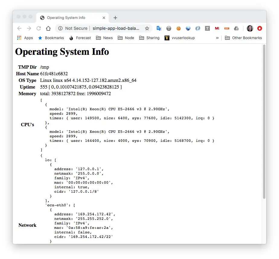
This is success. The domain name is for the load balancer, the load balancer connects to the NGINX container, and the NGINX container connects to the back-end application.
Cleanup
The terraform command has many sub-commands to deal with various lifecycle stages of an application deployment.
After you're done with the system, you might want to tear it down.
$ terraform destroy
... much output
Terraform will perform the following actions:

  # aws_alb.main will be destroyed
  - resource "aws_alb" "main" {
      - arn                        = "arn:aws:elasticloadbalancing:us-west-2:098106984154:loadbalancer/app/simple-app-load-balancer/ec77ca435e961e0f" -> null
      - arn_suffix                 = "app/simple-app-load-balancer/ec77ca435e961e0f" -> null
      - dns_name                   = "simple-app-load-balancer-1512130265.us-west-2.elb.amazonaws.com" -> null
      - drop_invalid_header_fields = false -> null
      - enable_deletion_protection = false -> null
      - enable_http2               = true -> null
      - id                         = "arn:aws:elasticloadbalancing:us-west-2:098106984154:loadbalancer/app/simple-app-load-balancer/ec77ca435e961e0f" -> null
      - idle_timeout               = 60 -> null
      - internal                   = false -> null
      - ip_address_type            = "ipv4" -> null
      - load_balancer_type         = "application" -> null
      - name                       = "simple-app-load-balancer" -> null
      - security_groups            = [
          - "sg-0d35f92f8cf18ffdd",
        ] -> null
      - subnets                    = [
          - "subnet-020fac77401651f51",
          - "subnet-0ac5b99290c6f8413",
        ] -> null
      - tags                       = {} -> null
      - vpc_id                     = "vpc-036443cb61655ce00" -> null
      - zone_id                    = "Z1H1FL5HABSF5" -> null

      - access_logs {
          - enabled = false -> null
        }

      - subnet_mapping {
          - subnet_id = "subnet-020fac77401651f51" -> null
        }
      - subnet_mapping {
          - subnet_id = "subnet-0ac5b99290c6f8413" -> null
        }
    }
... much output
Plan: 0 to add, 0 to change, 32 to destroy.

Do you really want to destroy all resources?
  Terraform will destroy all your managed infrastructure, as shown above.
  There is no undo. Only 'yes' will be accepted to confirm.

  Enter a value: yes

aws_cloudwatch_log_stream.simple_app_log_stream: Destroying... [id=simple-app-nginx-log-stream]
aws_route.internet_access: Destroying... [id=r-rtb-0290b79f714428e661080289494]
aws_route_table_association.private[0]: Destroying... [id=rtbassoc-0f62b8554c922a1ce]
aws_iam_role_policy_attachment.ecs_auto_scale_role: Destroying... [id=myEcsAutoScaleRole-20200330190715702800000002]

... much output

Destroy complete! Resources: 32 destroyed.
As you see from the output, Terraform analyzes the local files, and the installed infrastructure, making a map of everything that's involved. It then asks for your confirmation. If you say yes it goes and deletes everything in the installed system.
Summary
We've learned a lot in this post about using Terraform to construct an AWS ECS deployment of a multi-tier application.
We learned that with Terraform we can describe in fairly precise detail the architecture of an AWS VPC, various AWS resources, and deploy some Docker containers into an ECS cluster.
The system was simplified to have several instances of one service. This means that scaling (increasing or decreasing) the instances means the number of NGINX and Node.js containers increase or decrease in lock step. It's more likely that the two need to scale at different rates. Therefore this example should be refactored to use two Services, and hence two Task Definitions. But this blog post is long enough already.
Terraform is usable with a long list of cloud services. Many of them allows one to host Docker containers, and therefore we could use Terraform to deploy this service on other hosting platforms.
The code in this tutorial is derived from another tutorial
Deploying Containers on Amazon’s ECS using Fargate and Terraform: Part 2.

Books by David Herron
(Sponsored)