David Herron
Tags: Canon Photoshot Cameras »»»» Photography »»»» Infrared Photography »»»»
Digital camera sensors are often sensitive to infrared (IR) or ultraviolet (UV) light. The manufacturers add filters to cut out that unwanted light in order to have sharp images. To do infrared photography requires removing that filter, the IR/Cut filter, allowing the digital camera sensor to see infrared light. Given the success I've had with a Lumix DMC-ZS3 converted to Infrared, I wanted a better camera for the purpose. I found a Canon Powershot SX530 and found that it would be possible to convert it for infrared photography. While it doesn't natively shoot RAW mode pictures, the CHDK firmware can add that ability plus a whole lot more. Further with an adapter you can attach filters to the front of the SX530, making it far more suitable for infrared photography than the ZS3.
The Canon SX530 is what's now called a Bridge Camera. This means it's in between, or a bridge between, the smaller point-and-shoot cameras and the mirrorless or DSLR cameras. The mirrorless or DSLR cameras have more advanced abilities and interchangeable lenses, making them attractive to those with more photography knowledge. The simple point-and-shoots are designed primarily for recreational photography, literally pointing at things and shooting the camera. The bridge cameras used to be called Prosumer cameras, and have some advanced capabilities while not having an interchangeable lens and being designed to be somewhat simpler to use.
The SX530 has a massive zoom range - 50x - and it supports a lot of powerful features. It's a worthy camera for all kinds of photography. Plus, nowadays it is relatively affordable, being available on eBay for $150 or so.
The SX530 is attractive for infrared photography because of the possibility to attach filters to the front. You'd convert the SX530 to be a full spectrum camera (remove the IR/Cut filter) then attach the infrared filter to the camera. You could use different filters for different occasions, and can even attach an IR/Cut filter to take regular pictures.
General process for DIY conversion of digital cameras to shot infrared photography
To reiterate what I said in DIY Convert Lumix DMC-ZS3 for infrared or full spectrum photography - The process is:
- Disassemble enough of the camera to access the back of the lens assembly
- Determine how the Infrared/Ultraviolet Cut Filter is installed
- Usually the IR/Cut filter is part of a plate holding the sensor to the back of the lens assembly
- Remove that plate, remove the IR/Cut filter, clean out any dust, then reattach the sensor plate
- Reassemble the camera
The Canon SX530 is a more complex camera assembly than the Lumix ZS3. Fortunately the folks at iFixit have a
guide for getting in to the SX530 lens assembly. This guide is mostly accurate and was very useful.
Canon's LENS ERROR problem
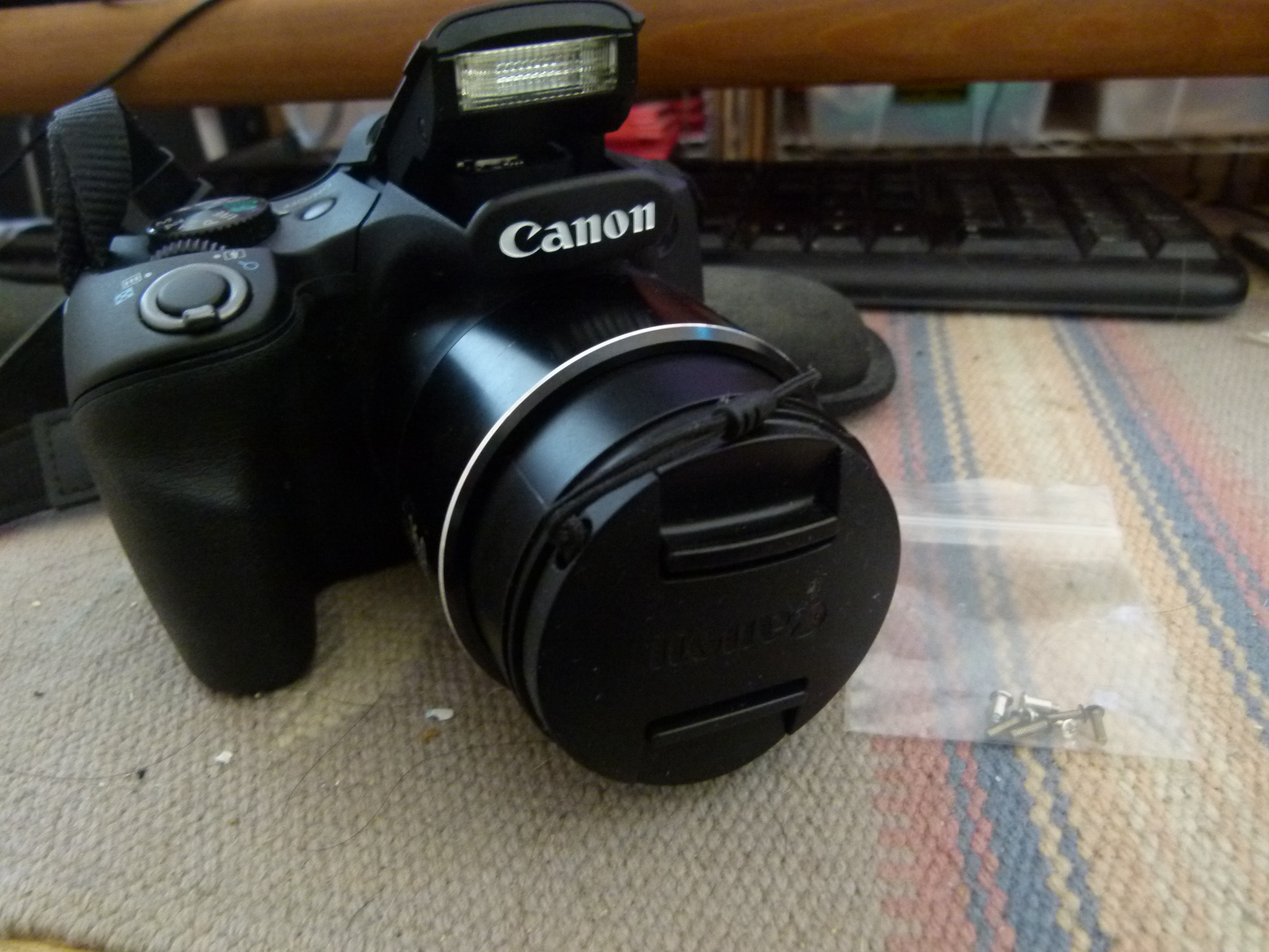
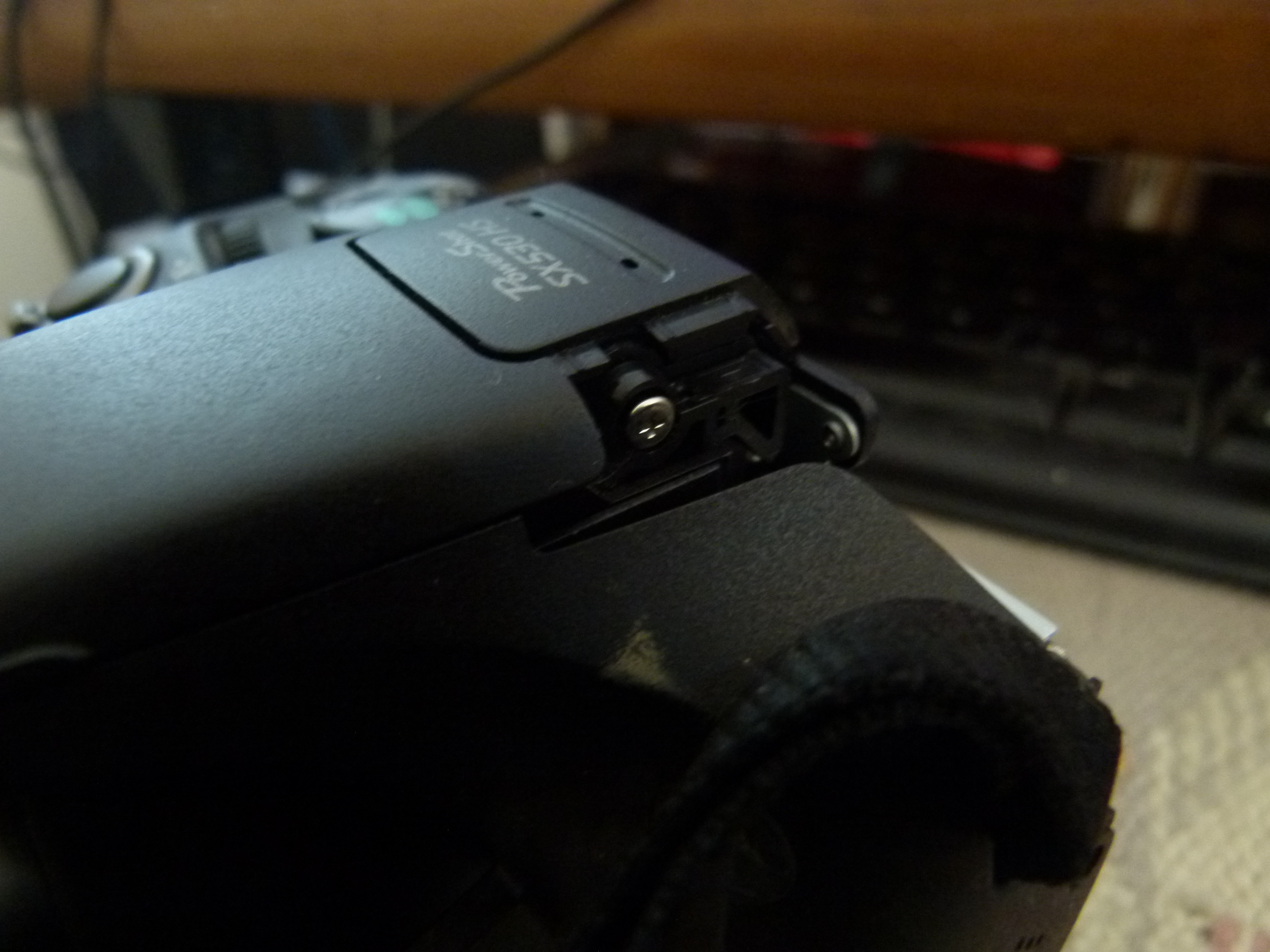
The sharp eyed will notice that this camera is not exactly well put together. This is because of a problem which arose during the process. This camera suffered from an issue common to certain Canon camera models, and I wanted to not only do the infrared conversion but attempt to fix that issue. But I botched the attempt to repair the camera.
Take the following as a warning to be careful about proceeding with an infrared conversion of the SX530. Using a Canon camera for infrared is interesting because of the CHDK firmware. But the difficulty level of this project is fairly high.
This Canon SX530 has the dreaded "LENS ERROR" issue. When turning the camera on the display would briefly show what was seen through the lens, and then display LENS ERROR, RESTART CAMERA. Before buying this camera I did not know about the LENS ERROR failure mode, but I've since learned this happens in lots of Canon Powershot models. Basically this makes the camera useless because the camera simply shuts itself down.
There's lots of advice out there saying a Canon camera with the LENS ERROR problem is not worth fixing. Maybe it's fixable, but the cost to hire someone to fix it is more than the camera is worth. But it also seemed possible that by extracting the lens I could possibly take apart and repair the lens assembly.
I thought that I could do two things at once. Sometimes I could hear the servo motor and gears not quite meshing, and it seemed possible to fix this up. And at the same time, I could performing an infrared conversion on the camera because I'd be into the lens assembly.
Unfortunately I made a horrible mistake while removing the lens assembly. One of the ribbon cable mounts was accidentally detached from the logic board, rendering the camera useless.
My plan of action was to extricate the lens assembly, see how it fits together, and make sure the lens tubes are lined up correctly. But screwing up that ribbon cable means I am unable to verify whether that plan of action would have created a solution for the Canon SX530 LENS ERROR problem.
Still the data I gathered shows how to perform an infrared conversion on the SX530. The conversion process does not require extricating the lens assembly from the camera.
Process for converting Canon SX530 to Infrared
It will be useful to refer to the iFixit
guide for getting in to the SX530 lens assembly while reading this tutorial.
This shows locations for various screws that hold the back half of the camera in place. Simply take a #000 Philips screwdriver and remove all the screws. Make sure to keep them in separate piles because there are 3 different screw lengths.
The back cover is a little tricky to extricate. I started at the left side, inserting a thumbnail into a crack to lift the back up. Then gently go around, making sure to carefully pull tabs out of slots.
First time I opened this up I didn't see how to proceed, and closed it back up. But the iFixit instructions make it clear what to do.
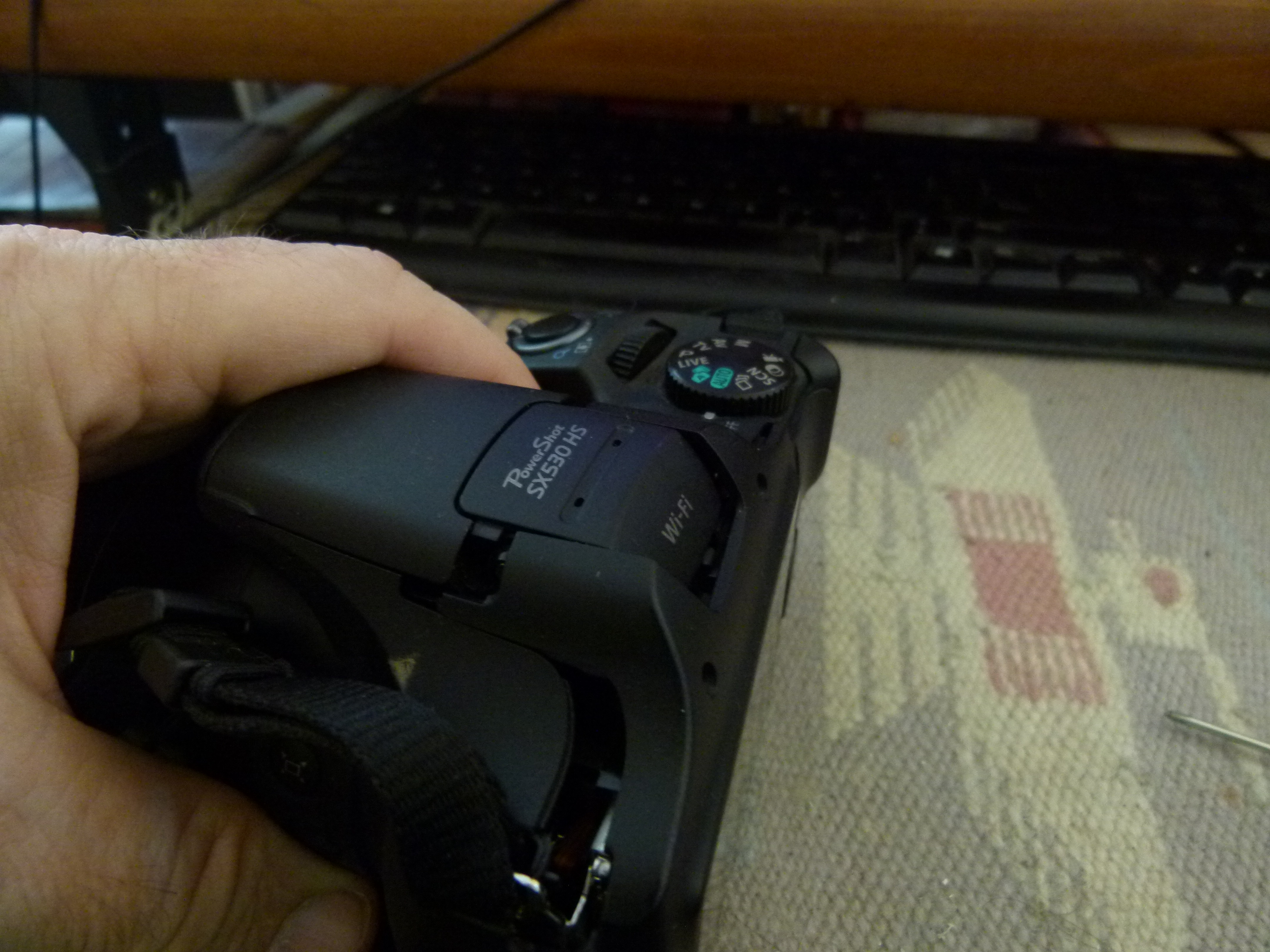
There are two screws holding down the microphone assembly. Simply remove those screws, again keeping them in a separate pile. These are different length (and color) than all the other screws.
To remove this assembly simply lift it upward, however this will take a little bit of jiggling. It helps a lot to lift the flash unit. The microphone assembly is rooted to the camera with a twisted-pair wire for the microphones. The wires are carefully threaded through some other parts, so carefully unthread the wires and carefully remember how they came out.
Let this unit dangle to the side. You won't have to remove it.
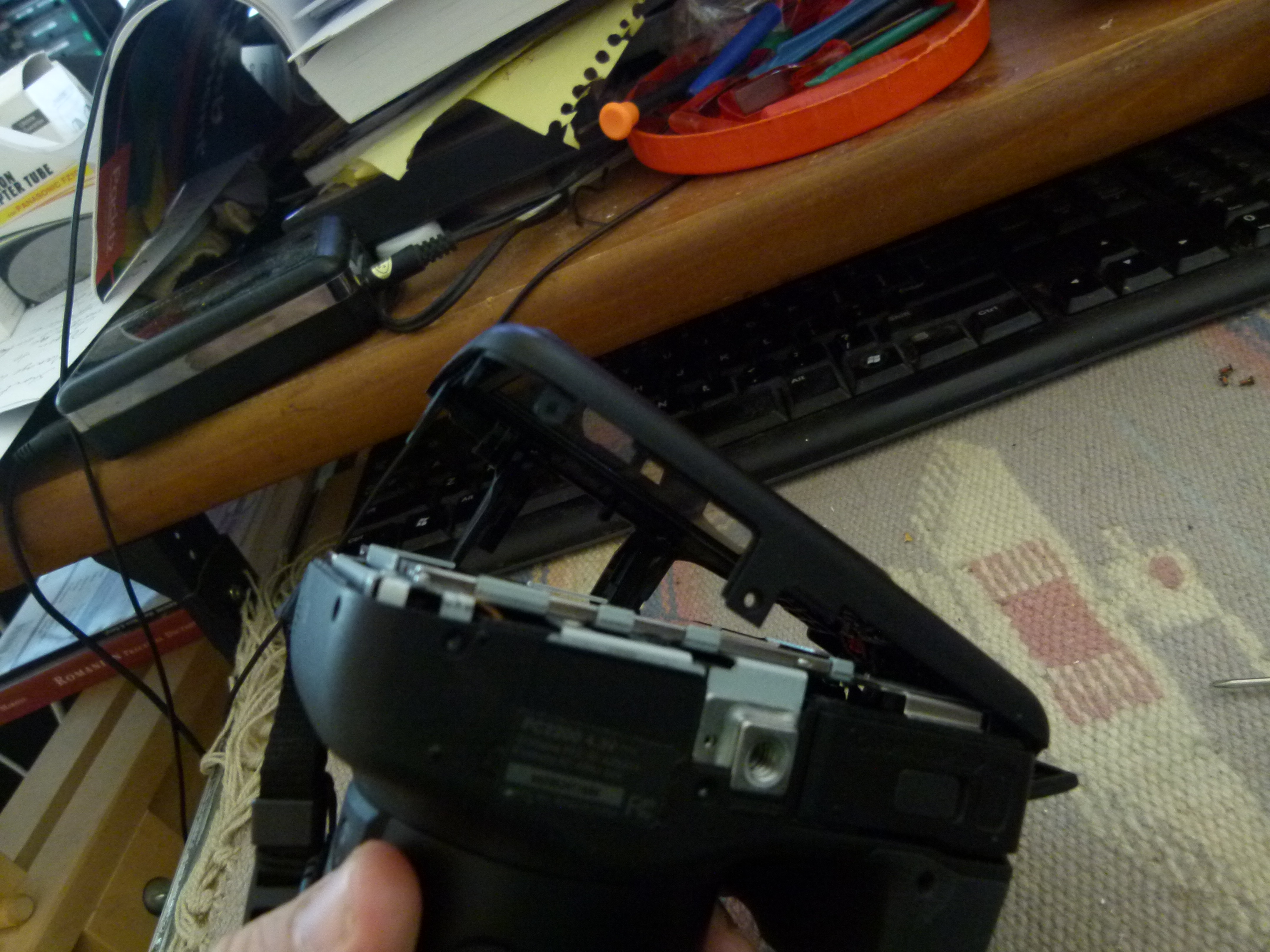
Removing the shutter module I found to be tricky. I could get it to lift up like this not using the method iFixit recommended, but taking a spudger along one of the cracks and twisting. It lifted up partly but never fully free'd up. Fortunately it's not necessary to remove this unit, and it's fine to leave it dangling loose.
Removing the microphone and shutter modules are done solely to free up access to other parts. Neither part has to be completely removed from the camera. Instead they just need to be moved out of the way.
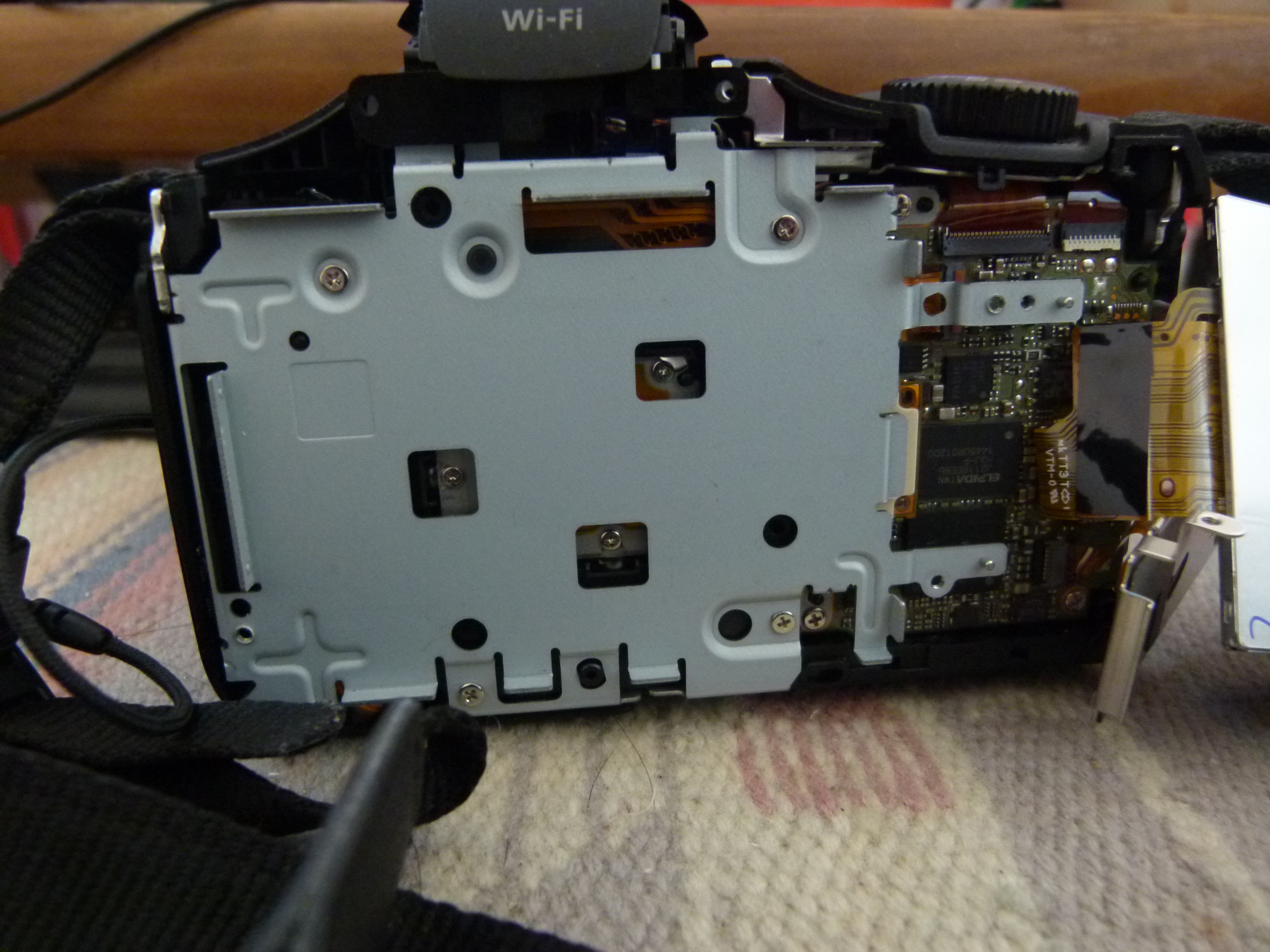
This plate must be removed to make it easier to deal with the LCD display. There are four screws holding it in place. Once those screws are removed it fairly easily lifts up. You can simply leave the plate dangling to the side rather than removing it as iFixit says to do.
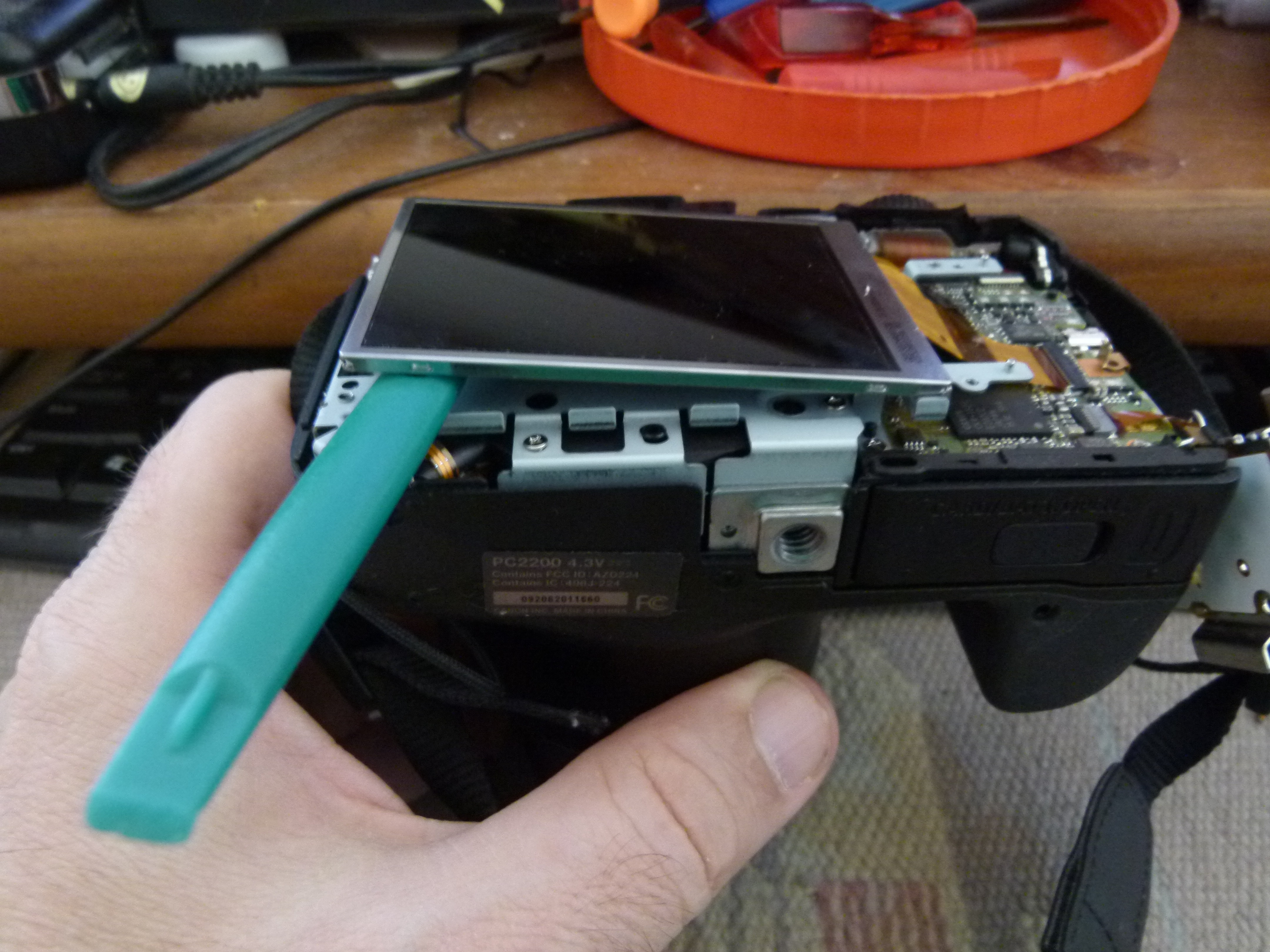
The LCD display is fairly easy to remove. As shown, just slide in a spudger and lift. There is a small bit of sticky tape holding it in place. The display is attached to the logic board using a ribbon cable. If desired you can detach the LCD display, but I left it attached with it dangling to the side.
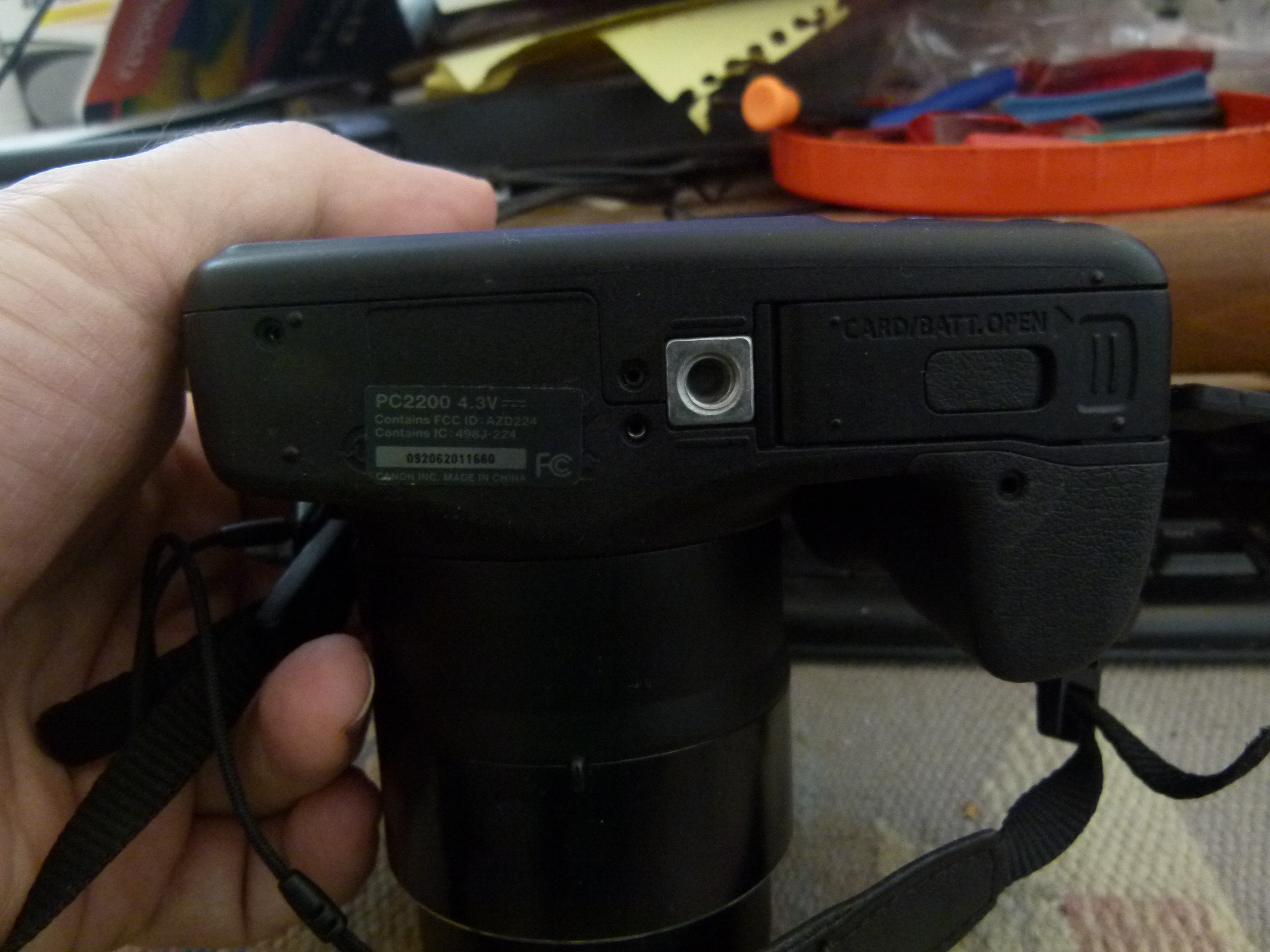
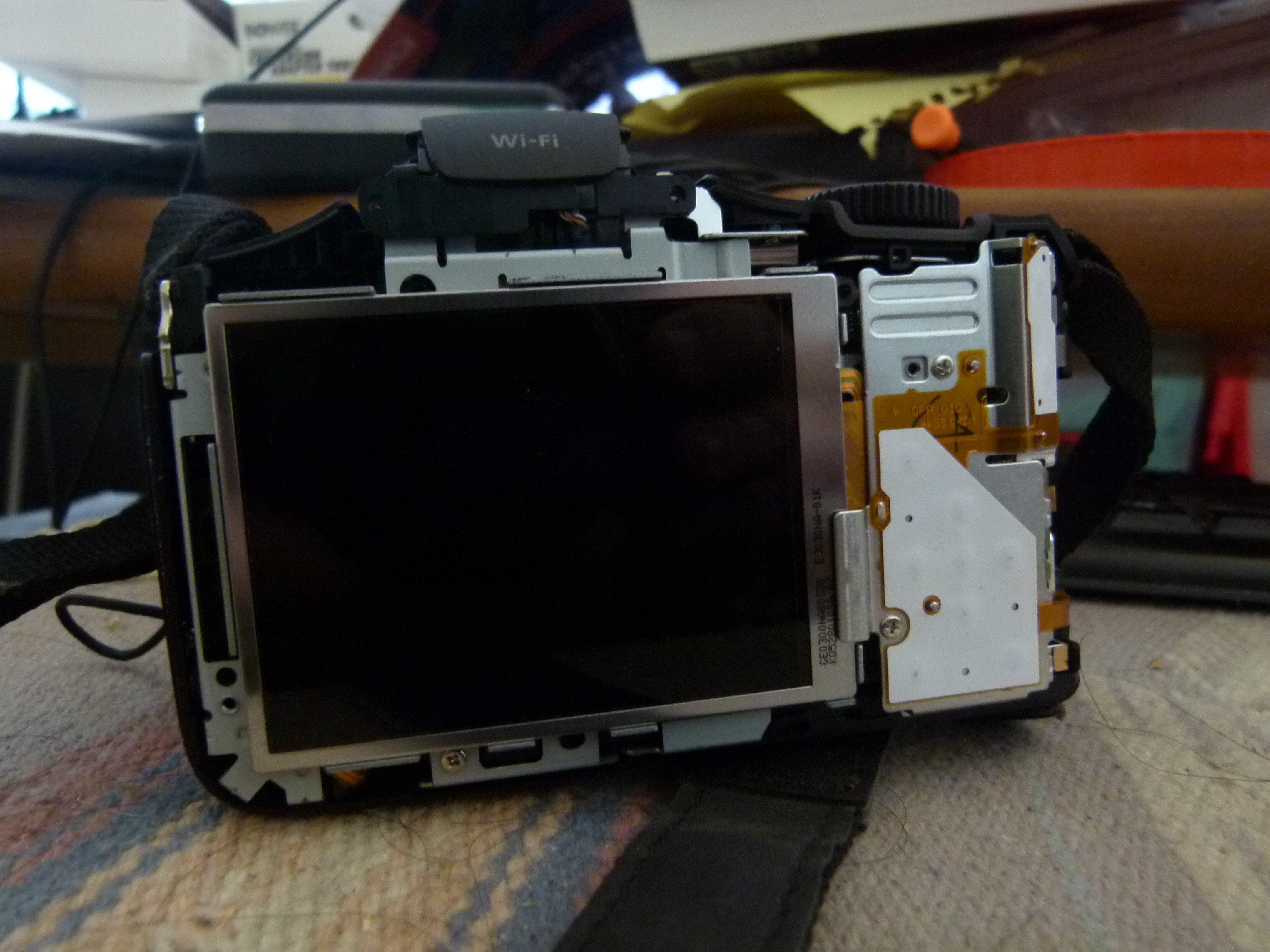
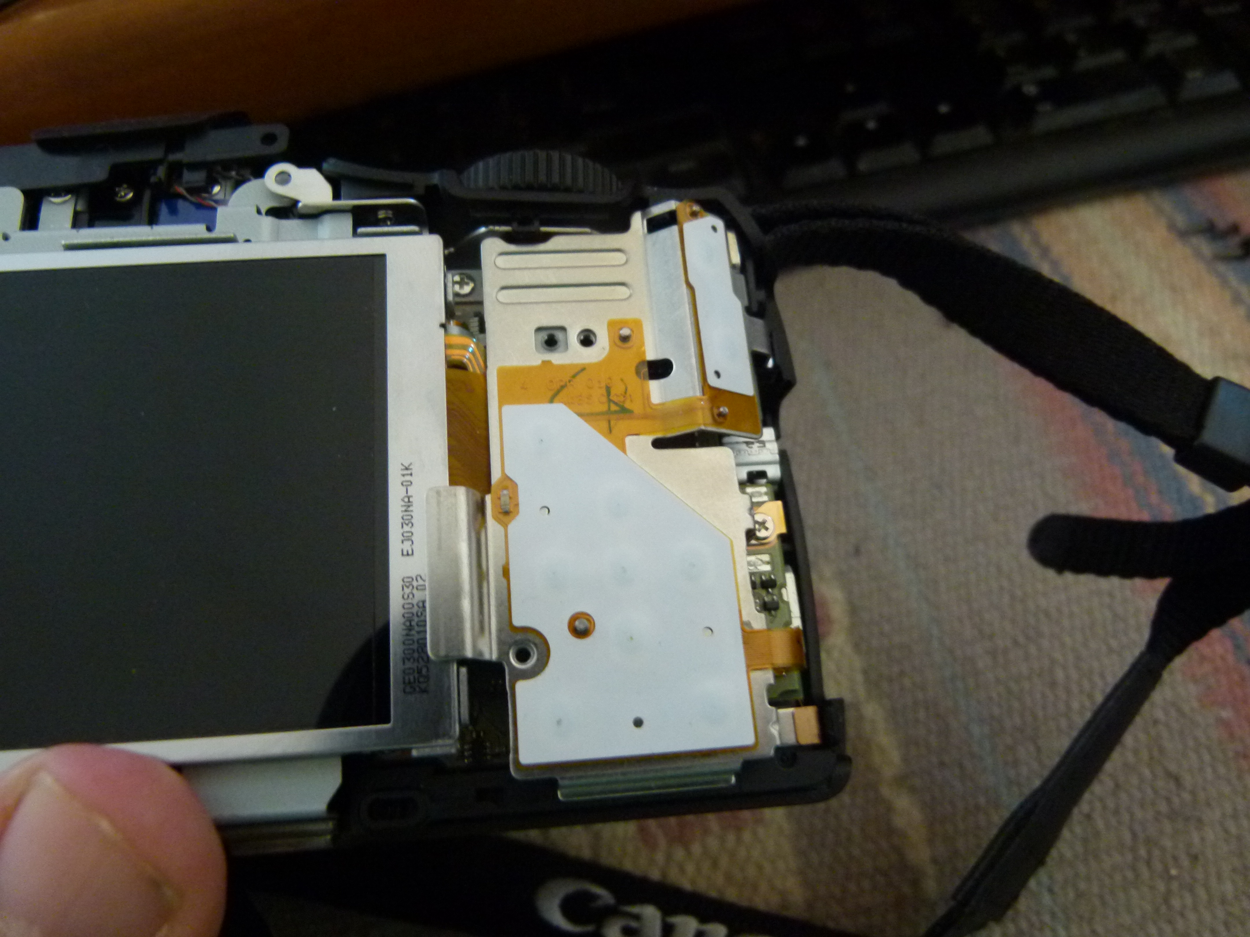
This metal plate is between you and the back of the lens unit.
There are at least eight screws holding this in place. They're all of different length. Unscrew them, making a separate pile for each.
Removing the plate is of course more complicated than just lifting it out. A part of the plate is lodged behind other parts, and the plate has fingers sticking deeply into recesses in the camera. Just be careful and it'll come out.
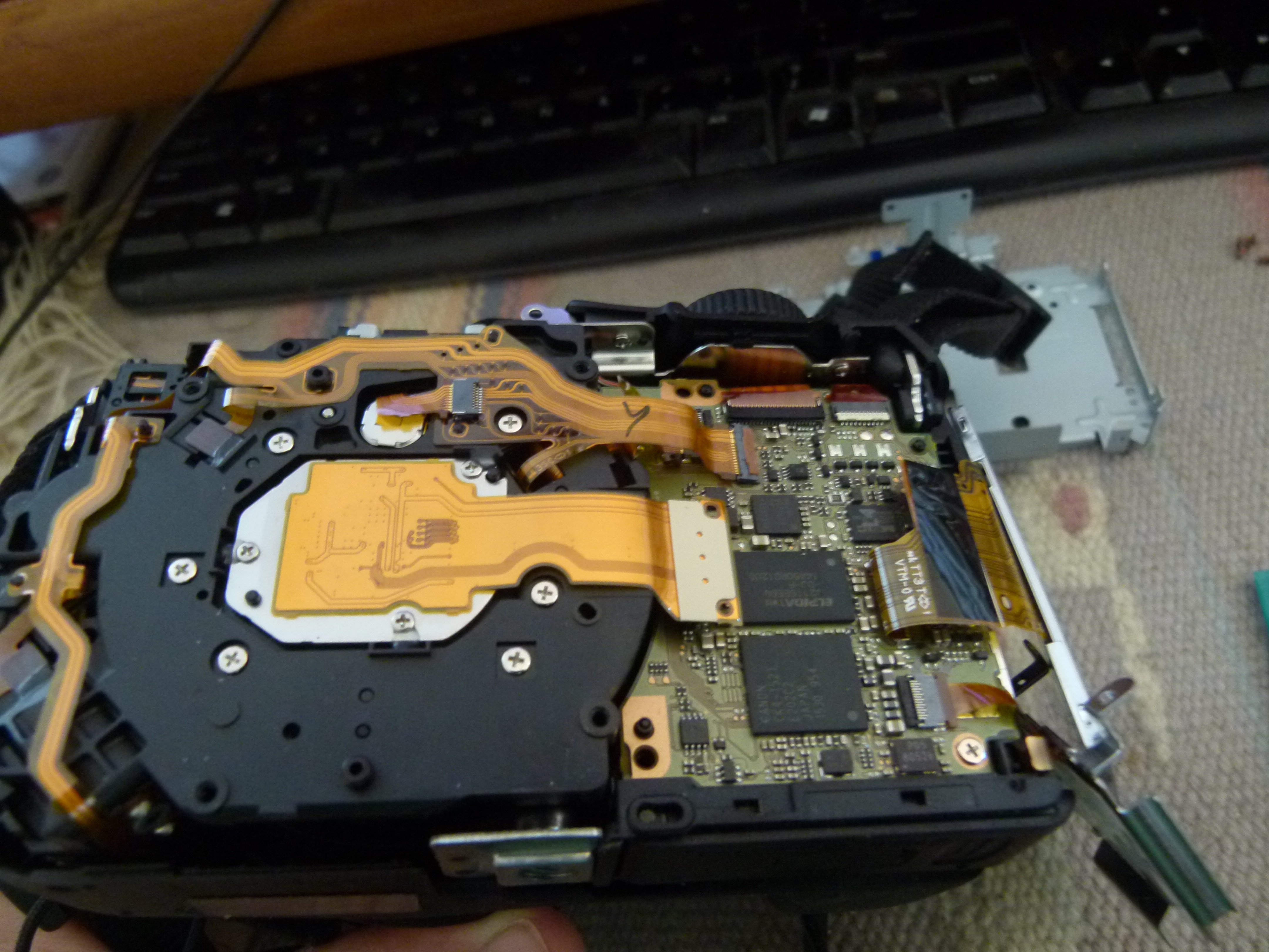
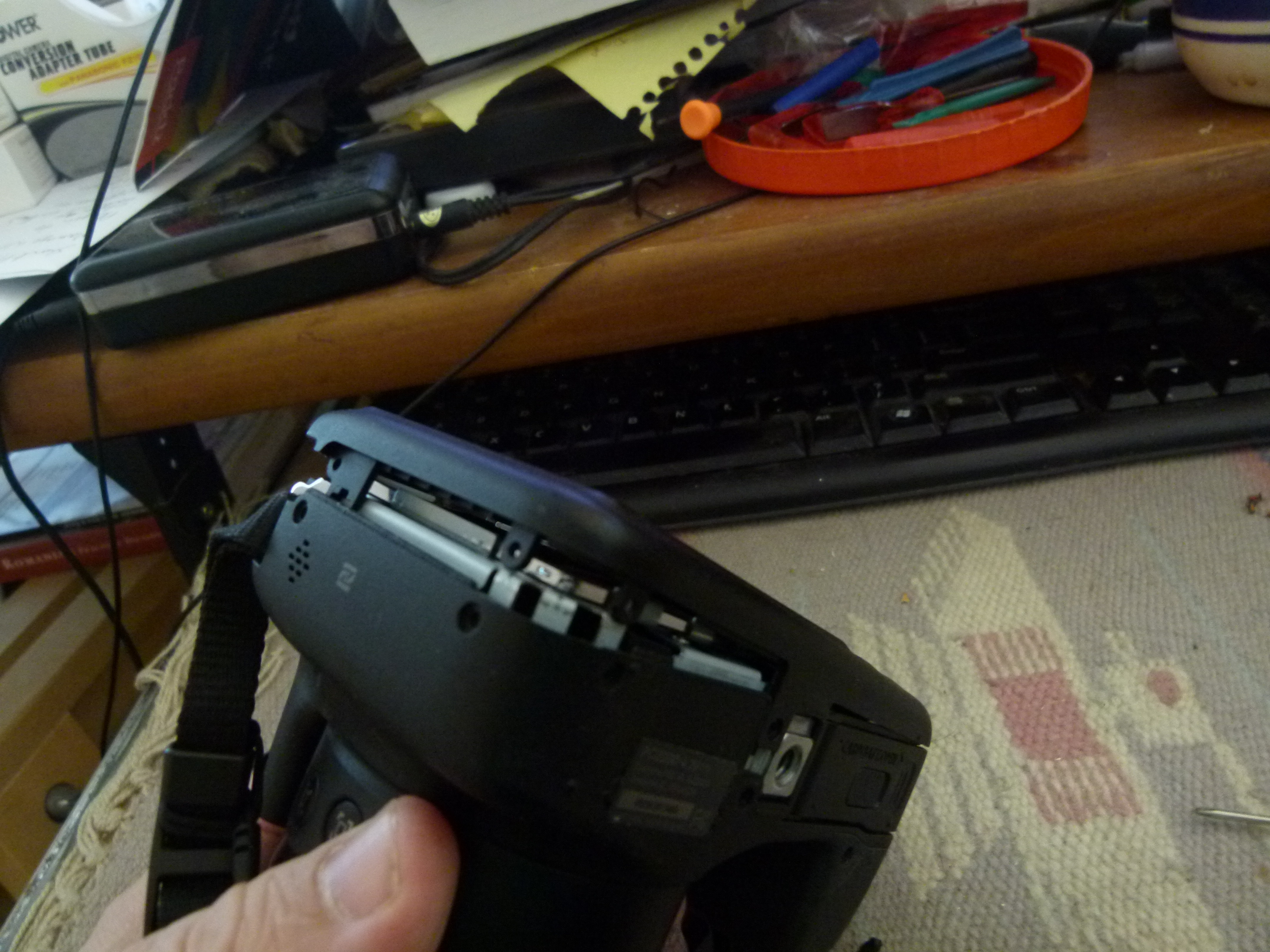
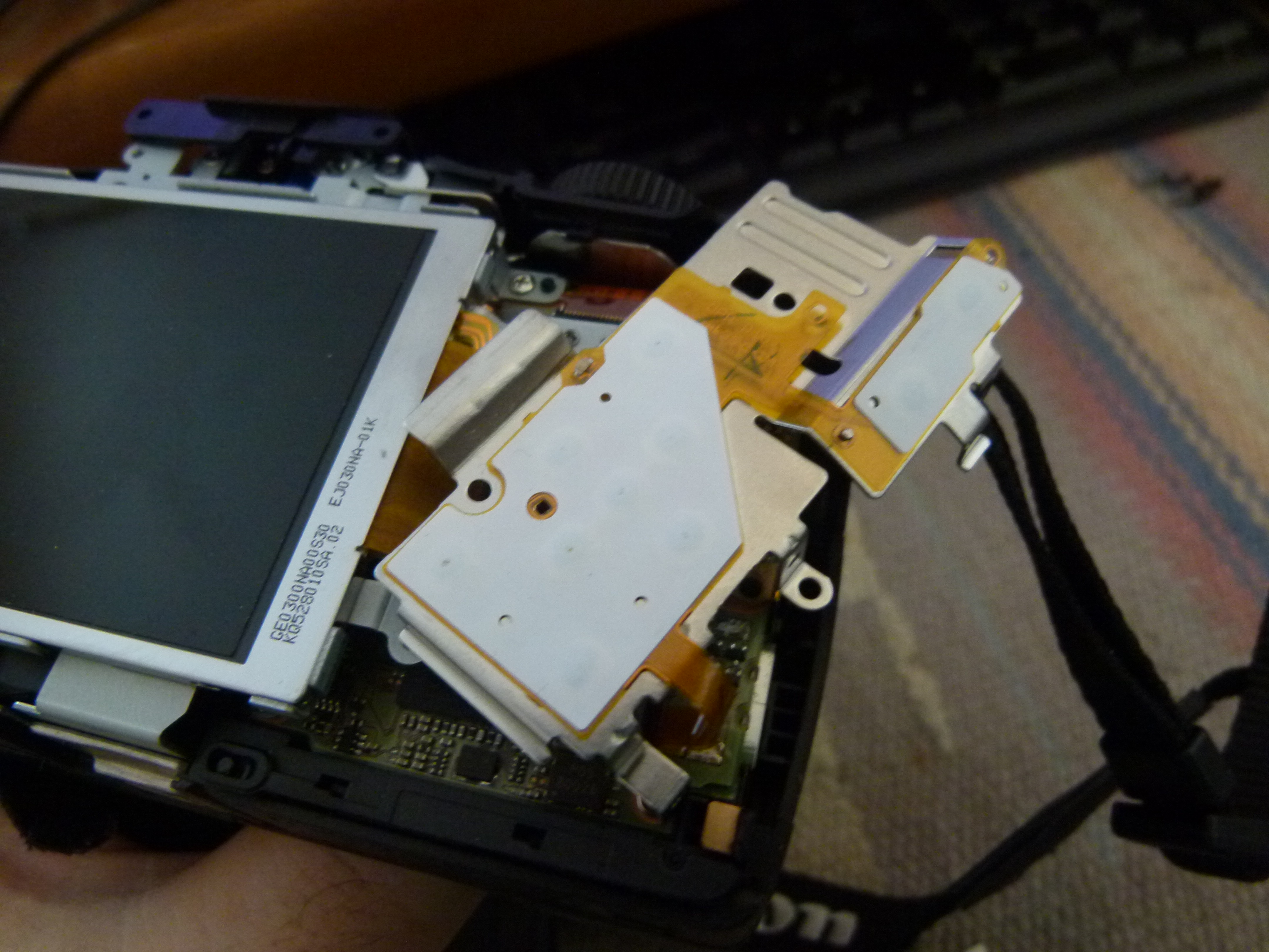
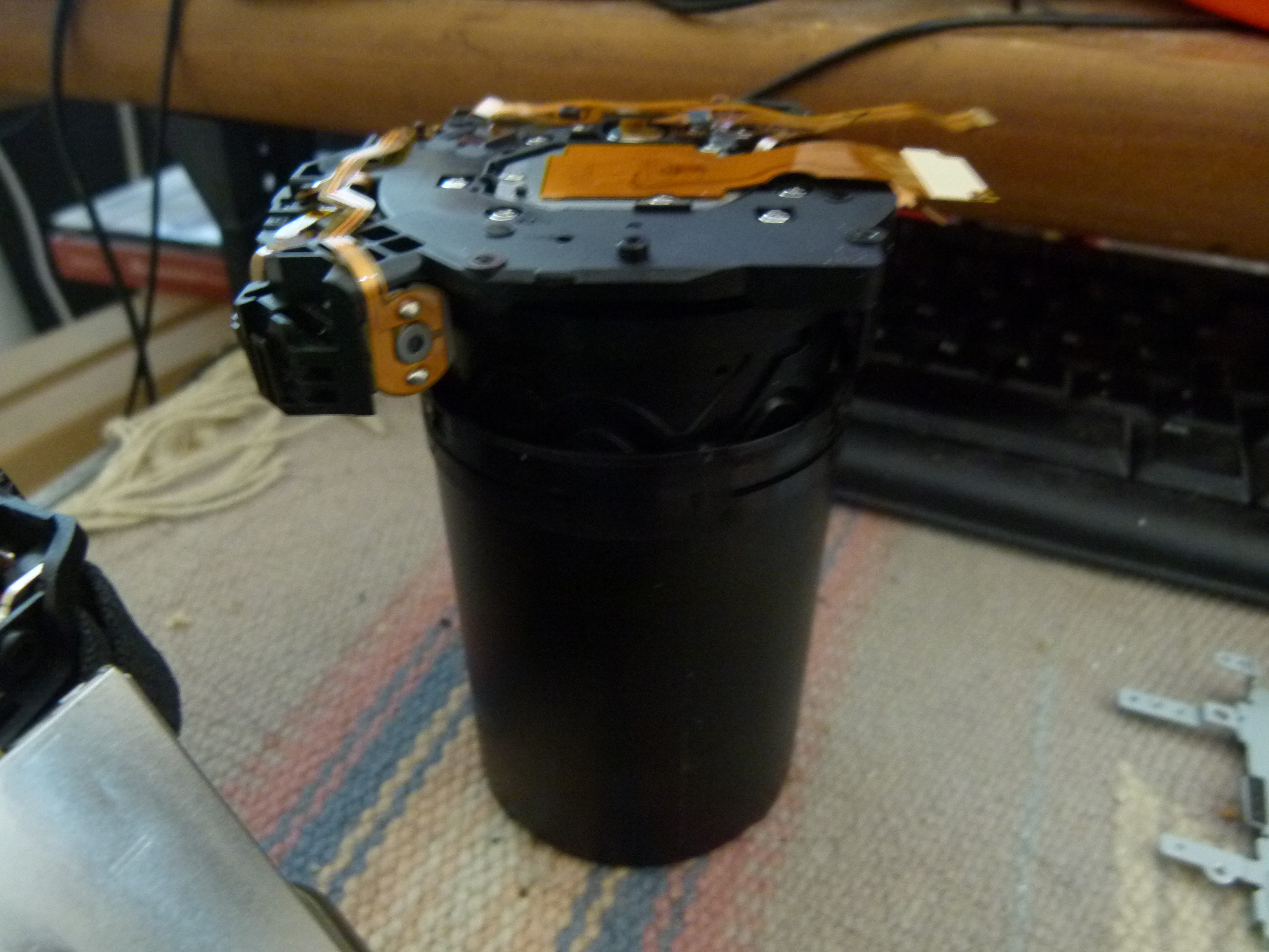
This is the back of the lens assembly. The silver plate holds the camera sensor, and there are three ribbon cables attaching it to the logic board.
At this point the lens assembly is floating fairly loosely. You'll need to be careful to avoid yanking out the ribbon cables or causing other issues.
For the purpose of an infrared conversion -- I did not do these steps, so I'm taking my best guess. There are three screws on the silver plate. It looks like there is some glue on each screw. Therefore you'll need to scrape away the glue, then unscrew these screws.
Under the plate will be the sensor as well as an IR/Cut filter. It probably looks like the sensor plate here: DIY Convert Lumix DMC-ZS3 for infrared or full spectrum photography
That is, there is probably a rubber gasket holding the filter in place. Lift out the filter, then replace the gasket, then screw down the sensor plate again.
This area is very sensitive to dust. Given the difficulty there is to get to this place it might be a good idea to use a Q-Tip cotton swab to clean up any dust that might be there.
From this point simply close up the camera by reversing the steps above.
Where my process botched is when trying to remove the ribbon cables from the lens assembly to the logic board. If your goal is to remove the lens assembly, then those cables must be detached. Two of them are easy, but ... The cable in the middle - instead of removing the cable, the connector got torn off the logic board.
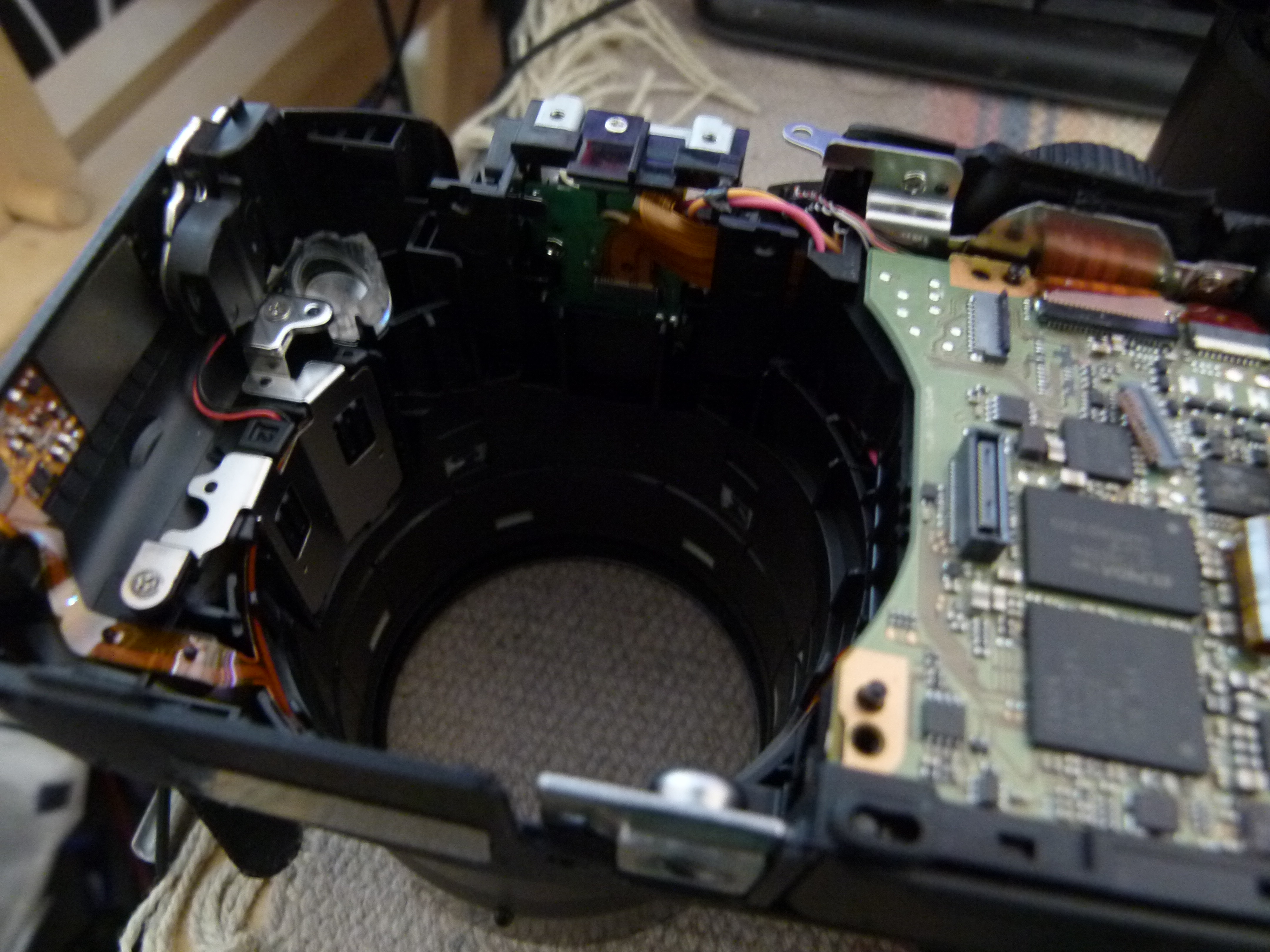
If you're adventurous, you can remove this and ogle at the machinery. But I really do not recommend doing so.


")